Blog Entry
Build Your Own Microcontroller Based PID Control Line Follower Robot (LFR) – Second Part
August 30, 2009 by rwb, under Robotics.
One of the interesting parts in building the Line Follower Robot is; you could start it with a very simple version by using just two transistors with the LED and LDR for sensor (Build Your Own Transistor Based Mobile Line Follower Robot – First Part) and enhance it to the programmable version that use microcontroller as the brain for controlling the robot. The reason of using the microcontroller for the Line Follower Robot is we need to make more robust, reliable and flexible robot which you could not have it from the discrete electronics component robot without changing most of the electronic circuit design.

The advantages in building the microcontroller based Line Follower Robot (LFR) is we could take the advantage of microcontroller’s ALU (Arithmetic Logic Unit) to compute mathematics equation to perform the industrial standard Proportional, Integral and Derivative control or known as PID control. On this tutorial we will learn to build the LFR using the powerful Atmel AVR ATMega168 microcontroller and at the same time we will learn to utilize many of the AVR ATMega168 microcontroller sophisticated features to support our Line Follower Robot.
Now let’s check out all the exciting features of this Line Follower Robot that we are going to build:
- Fully implement the industrial standard Proportional, Integral and Derivative (PID) control with flexible PID tuning parameter using the AVR ATMega168 UART peripheral and store the parameter to the AVR ATMega168 microcontroller build-in 512 Bytes EEPROM
- Use five infra red reflective object sensor for the black line sensor with Microchip MCP23008 8-bit I2C (read as I square C) I/O expander chip to talk to the AVR ATMega168 Microcontroller I2C peripheral
- 4.5 Volt to 5 Volt DC to DC Step-Up using Maxim MAX756 for powering both the electronics circuits and the DC motors. This will ensure the electronics circuits and the DC motors keep working properly even though the battery voltage level drops below 4.5 Volt.
- Use the AVR ATMega168 ADC (Analog to Digital Converter) peripheral to control the maximum speed of the robot.
- Use the AVR ATMega168 PWM (Pulse Width Modulation) peripheral to drive the SGS-Thomson L293D chip to control the DC motors speed
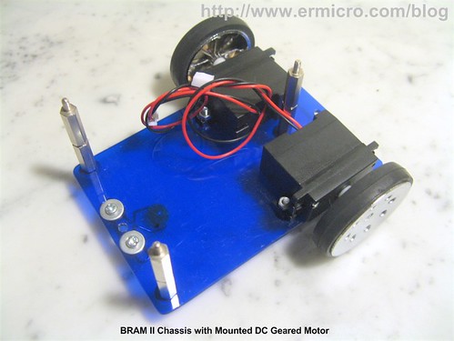
BRAM II Chassis Construction
The first version of BRAM (Beginner’s Robot Autonomous Mobile), used CD/DVD for the chassis; in this version of BRAM, I use the acrylic as the base for the chassis; which is easy to shape, drill and it came with transparent look and many color to choose too. You could read more information about the first BRAM version on my previous posted blog Building BRAM your first Autonomous Mobile Robot Using Microchip PIC Microcontroller.

BRAM II construction material parts:
- Acrylic for the BRAM chassis
- Two geared DC motors with wheels rated 4.5 to 5 volt (25-30mA) with the wheel or you could use the modified servo motor (it’s a servo motor without the electronics’s control board)
- One 3 x 1.5 volt AA battery holder with on-off switch
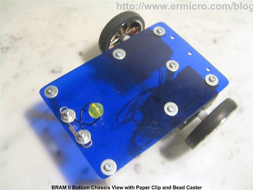
- One plastic bead (usually it use for the neck less) and one paper clip for the caster
- Enough nuts, bolts and PCB (printed circuit board) standoff.
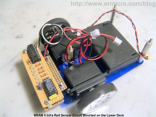
BRAM construction consists of two decks, where the lower deck is used to hold the battery, DC motors and the sensor circuit while the upper deck is used to hold the motor controller circuit and the AVRJazz Mega168 board.
Put the 3xAA battery and sensor circuit on the lower deck and the motor control circuit at the bottom of the upper deck.
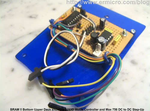
Now connect the battery power terminal, sensor circuit power terminal, DC motor power terminal to the Motor Control Circuit and screw the upper deck on the lower deck.
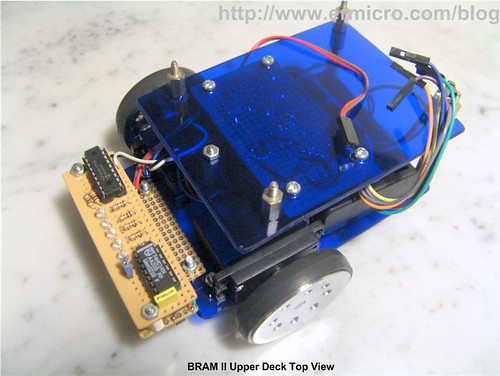
Finally put the AVRJazz Mega168 board on top of the upper deck and connect all the connectors from the Motor Control Circuit and Sensor Circuit to the AVRJazz Mega168 board, now you are ready to program the robot.
BRAM II Electronic Circuit and Program
BRAM II use quite sophisticated power mechanism circuit as well as the line sensor circuit design to make it more robust line follower robot.
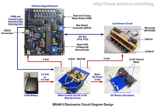
The 3xAA battery is the main power source for both the electronics circuits and the DC motors, because the Line Follower Robot need to accurately control the motor speed and tracking the line; therefore BRAM II design use DC to DC step-up circuit to boost 4.5 volt level up to the 5 volt level using the Maxim MAX756, you could read more about MAX756 in my previous posted blog Powering your Microcontroller’s Based Project. The advantages of using the power boost is all the electronics circuits and DC motors will guarantee to get proper voltage level even though the main power source theoretically drops down to 2 volt level; although I’ve never try this.
For the DC motors controller we simply use the two channels SGS-Thomson L293D H-Bridge motor driver chips, this chip is used to make circuit simpler and robust compared to the standard transistor’s base H-Bridge driver. The L293D chip is able to handle non repetitive current up to 1.2 A for each channels and its already equipped with the internal EMF (Electromotive Force) protection diodes.
For the line sensor circuit I decided to take advantage of the Microchip MCP23008 I2C 8-bit I/O expander to minimized the AVR Mega168 microcontroller I/O ports usage and at the same time it serve as a learning tools of how to expand your microcontroller I/O port using the Microchip MCP23008. Here is the complete PDF schematic for the AVRJazz Mega168 board, Motor Controller & DC to DC Step-Up and the Sensor Circuit.
The last is the ATMega168 UART peripheral, which is used to setup our BRAM II PID control parameter; by using the AVRJazz Mega168 board build in RS323 voltage level converter; we could connect the RS232 communication (COM) port directly to the computer COM port or you could use the USB to RS232 converter as I did and use the MS Windows HyperTerminal or puTTY program to enter the PID control setup. You could read more about AVR UART peripheral on my previous posted blog Working with AVR microcontroller Communication Port Project.
The following are the list of hardware and software used in this tutorial:
- Supporting chips: SGS Thomson L293D, Maxim MAX756, Microchip MCP23008 and 74HC14 Schmitt trigger
- Five Junye JY209-01 reflective object sensor.
- For the detail electronics components such as transistors, capacitors and resistors please refer to the schematic above.
- AVRJazz Mega168 board from ermicro which base on the AVR ATmega168 microcontroller.
- WinAVR for the GNU’s C compiler v4.3.0 (WinAVR 2009313).
- Atmel AVR Studio v4.17 for the coding and debugging environment.
- STK500 programmer from AVR Studio 4, using the AVRJazz Mega168 board STK500 v2.0 bootloader facility.
Ok that’s a brief explanation of the BRAM II Line Follower Robot project electronic circuits that we are going to build; now let’s take a look at the C code that makes the BRAM II brain:
//***************************************************************************
//  File Name	 : bramlfr.c
//  Version	 : 1.0
//  Description  : BRAM Line Follower Robot (LFR)
//               : LFR with PID Controller
//  Author       : RWB
//  Target       : AVRJazz Mega168 Board
//  Compiler     : AVR-GCC 4.3.0; avr-libc 1.6.2 (WinAVR 20090313)
//  IDE          : Atmel AVR Studio 4.17
//  Programmer   : AVRJazz Mega168 STK500 v2.0 Bootloader
//               : AVR Visual Studio 4.17, STK500 programmer
//  Last Updated : 28 July 2009
//***************************************************************************
#include <avr/io.h>
#include <util/delay.h>
#include <avr/interrupt.h>
#include <compat/twi.h>
#include <stdio.h>
#include <avr/pgmspace.h>
#include <avr/eeprom.h>
// BRAM Debugging Mode, 0-Debug Off, 1-Debug On
#define BRAM_DEBUG 0
#define BAUD_RATE 19200
#define MAX_TRIES 50
#define MCP23008_ID    0x40  // MCP23008 Device Identifier
#define MCP23008_ADDR  0x0E  // MCP23008 Device Address
#define IODIR 0x00           // MCP23008 I/O Direction Register
#define GPPU  0x06           // MCP23008 I/O Pull-Up Resistor Register
#define GPIO  0x09           // MCP23008 General Purpose I/O Register
#define I2C_START 0
#define I2C_DATA 1
#define I2C_DATA_ACK 2
#define I2C_STOP 3
#define ACK 1
#define NACK 0
// Define BRAM Steering
#define MOVE_FORWARD  0
#define TURN_LEFT     1
#define TURN_RIGHT    2
#define ROTATE_LEFT   3
#define ROTATE_RIGHT  4
#define MOVE_BACKWARD 5
#define FULL_STOP     6
// Define BRAM Sensor
#define MAX_MAP 24
#define TARGET_VAL 60
#define MAX_SENSOR_MAP 120
// Define BRAM Variables
const unsigned int sensor_map[] PROGMEM = {
  0b00000,0,
  0b00001,10,
  0b00011,20,
  0b00010,30,
  0b00111,40,
  0b00110,50,
  0b00100,60,
  0b01100,70,
  0b11100,80,
  0b01000,90,
  0b11000,100,
  0b10000,110
};
unsigned char MaxSpeed;                         // Hold Motor Maximum Speed
unsigned int Kp,Ki,Kd;                          // PID Parameters
int prev_res=0, prev_err_1=0, prev_err_2=0;     // PID Control Variables
void uart_init(void)
{
  UBRR0H = (((F_CPU/BAUD_RATE)/16)-1)>>8;	// set baud rate
  UBRR0L = (((F_CPU/BAUD_RATE)/16)-1);
  UCSR0B = (1<<RXEN0)|(1<<TXEN0); 		// enable Rx & Tx
  UCSR0C=  (1<<UCSZ01)|(1<<UCSZ00);  	        // config USART; 8N1
}
void uart_flush(void)
{
  unsigned char dummy;
  while (UCSR0A & (1<<RXC0)) dummy = UDR0;
}
int uart_putch(char ch,FILE *stream)
{
   if (ch == '\n')
    uart_putch('\r', stream);
   while (!(UCSR0A & (1<<UDRE0)));
   UDR0=ch;
   return 0;
}
int uart_getch(FILE *stream)
{
   unsigned char ch;
   while (!(UCSR0A & (1<<RXC0)));
   ch=UDR0;

   /* Echo the Output Back to terminal */
   uart_putch(ch,stream);

   return ch;
}
void ansi_cl(void)
{
  // ANSI clear screen: cl=\E[H\E[J
  putchar(27);
  putchar('[');
  putchar('H');
  putchar(27);
  putchar('[');
  putchar('J');
}
void ansi_me(void)
{
  // ANSI turn off all attribute: me=\E[0m
  putchar(27);
  putchar('[');
  putchar('0');
  putchar('m');
}
void ansi_cm(unsigned char row,unsigned char col)
{
  // ANSI cursor movement: cl=\E%row;%colH
  putchar(27);
  putchar('[');
  printf("%d",row);
  putchar(';');
  printf("%d",col);
  putchar('H');
}
// BRAM Steering Function
// PD2 - Input 1 (Left Motor), PD3 - Input 2 (Left Motor)
// PD4 - Input 3 (Right Motor), PD7 - Input 4 (Right Motor)
void BRAM_Steer(unsigned char steer)
{
  switch(steer) {
    case MOVE_FORWARD:
	  PORTD &= ~(1 << PD4); PORTD |= (1 << PD7);  // Right Motor On Forward
	  PORTD &= ~(1 << PD2); PORTD |= (1 << PD3);  // Left Motor On Forward
      break;
    case TURN_LEFT:
  	  PORTD &= ~(1 << PD4); PORTD |= (1 << PD7);  // Right Motor On Forward
	  PORTD &= ~(1 << PD2); PORTD &= ~(1 << PD3); // Left Motor Off
      break;
    case TURN_RIGHT:
	  PORTD &= ~(1 << PD4); PORTD &= ~(1 << PD7); // Right Motor Off
	  PORTD &= ~(1 << PD2); PORTD |= (1 << PD3);  // Left Motor On Forward
      break;
    case ROTATE_LEFT:
 	  PORTD &= ~(1 << PD4); PORTD |= (1 << PD7);  // Right Motor On Forward
	  PORTD |= (1 << PD2); PORTD &= ~(1 << PD3);  // Left Motor On Reverse
          break;
    case ROTATE_RIGHT:
	  PORTD |= (1 << PD4); PORTD &= ~(1 << PD7);  // Right Motor On Reverse
	  PORTD &= ~(1 << PD2); PORTD |= (1 << PD3);  // Left Motor On Forward
          break;
    case MOVE_BACKWARD:
 	  PORTD |= (1 << PD4); PORTD &= ~(1 << PD7);  // Right Motor On Reverse
	  PORTD |= (1 << PD2); PORTD &= ~(1 << PD3);  // Left Motor On Reverse
          break;
    case FULL_STOP:
	  PORTD &= ~(1 << PD4); PORTD &= ~(1 << PD7);  // Right Motor Off
	  PORTD &= ~(1 << PD2); PORTD &= ~(1 << PD3);  // Left Motor Off
          break;
  }
}
// BRAM Motor Speed Control
// PD5 - OC0B -> ENB1 (Left Motor)
// PD6 - OC0A -> ENB2 (Right Motor)
void BRAM_DriveMotor(int left_speed, int right_speed)
{
  unsigned char left_pwm,right_pwm;
  if (left_speed >= 0 && right_speed >= 0) {
    // Move Forward
    BRAM_Steer(MOVE_FORWARD);

    left_pwm=left_speed;
    right_pwm=right_speed;
  } else if (left_speed < 0 && right_speed < 0) {
    // Move Backward
    BRAM_Steer(MOVE_BACKWARD);
    left_pwm=left_speed * -1;
    right_pwm=right_speed * -1;
  } else if (left_speed < 0 && right_speed >= 0) {
    // Rotate Left
    BRAM_Steer(ROTATE_LEFT);
    left_pwm=left_speed * -1;
    right_pwm=right_speed;
  } else if (left_speed >= 0 && right_speed < 0) {
    // Rotate Right
    BRAM_Steer(ROTATE_RIGHT);
    left_pwm=left_speed;
    right_pwm=right_speed * -1;
  } else {
    // Full Stop
    BRAM_Steer(FULL_STOP);
    left_pwm=0;
    right_pwm=0;
  }
  // Assigned the value to the PWM Output Compare Registers A and B
  OCR0A=right_pwm;
  OCR0B=left_pwm;
}
/* START I2C Routine */
unsigned char i2c_transmit(unsigned char type) {
  switch(type) {
     case I2C_START:    // Send Start Condition
       TWCR = (1 << TWINT) | (1 << TWSTA) | (1 << TWEN);
       break;
     case I2C_DATA:     // Send Data with No-Acknowledge
       TWCR = (1 << TWINT) | (1 << TWEN);
       break;
     case I2C_DATA_ACK: // Send Data with Acknowledge
       TWCR = (1 << TWEA) | (1 << TWINT) | (1 << TWEN);
       break;
     case I2C_STOP:     // Send Stop Condition
       TWCR = (1 << TWINT) | (1 << TWEN) | (1 << TWSTO);
       return 0;
  }
  // Wait for TWINT flag set on Register TWCR
  while (!(TWCR & (1 << TWINT)));
  // Return TWI Status Register, mask the prescaller bits (TWPS1,TWPS0)
  return (TWSR & 0xF8);
}
char i2c_start(unsigned int dev_id, unsigned int dev_addr, unsigned char rw_type)
{
  unsigned char n = 0;
  unsigned char twi_status;
  char r_val = -1;
i2c_retry:
  if (n++ >= MAX_TRIES) return r_val;
  // Transmit Start Condition
  twi_status=i2c_transmit(I2C_START);

  // Check the TWI Status
  if (twi_status == TW_MT_ARB_LOST) goto i2c_retry;
  if ((twi_status != TW_START) && (twi_status != TW_REP_START)) goto i2c_quit;
  // Send slave address (SLA_W)
  TWDR = (dev_id & 0xF0) | ((dev_addr << 1) & 0x0E) | rw_type;
  // Transmit I2C Data
  twi_status=i2c_transmit(I2C_DATA);
  // Check the TWSR status
  if ((twi_status == TW_MT_SLA_NACK) || (twi_status == TW_MT_ARB_LOST)) goto i2c_retry;
  if (twi_status != TW_MT_SLA_ACK) goto i2c_quit;
r_val=0;
i2c_quit:
  return r_val;
}
void i2c_stop(void)
{
  unsigned char twi_status;
  // Transmit I2C Data
  twi_status=i2c_transmit(I2C_STOP);
}
char i2c_write(char data)
{
  unsigned char twi_status;
  char r_val = -1;
  // Send the Data to I2C Bus
  TWDR = data;
  // Transmit I2C Data
  twi_status=i2c_transmit(I2C_DATA);
  // Check the TWSR status
  if (twi_status != TW_MT_DATA_ACK) goto i2c_quit;
r_val=0;
i2c_quit:
  return r_val;
}
char i2c_read(char *data,char ack_type)
{
  unsigned char twi_status;
  char r_val = -1;

  if (ack_type) {
    // Read I2C Data and Send Acknowledge
    twi_status=i2c_transmit(I2C_DATA_ACK);
    if (twi_status != TW_MR_DATA_ACK) goto i2c_quit;
  } else {
    // Read I2C Data and Send No Acknowledge
    twi_status=i2c_transmit(I2C_DATA);
    if (twi_status != TW_MR_DATA_NACK) goto i2c_quit;
  }
  // Get the Data
  *data=TWDR;
  r_val=0;
i2c_quit:
  return r_val;
}
void Write_MCP23008(unsigned char reg_addr,unsigned char data)
{
   // Start the I2C Write Transmission
   i2c_start(MCP23008_ID,MCP23008_ADDR,TW_WRITE);
   // Sending the Register Address
   i2c_write(reg_addr);
   // Write data to MCP23008 Register
   i2c_write(data);
   // Stop I2C Transmission
   i2c_stop();
}
unsigned char Read_MCP23008(unsigned char reg_addr)
{
   char data;
   // Start the I2C Write Transmission
   i2c_start(MCP23008_ID,MCP23008_ADDR,TW_WRITE);
   // Read data from MCP23008 Register Address
   i2c_write(reg_addr);
   // Stop I2C Transmission
   i2c_stop();

   // Re-Start the I2C Read Transmission
   i2c_start(MCP23008_ID,MCP23008_ADDR,TW_READ);
   i2c_read(&data,NACK);

   // Stop I2C Transmission
   i2c_stop();

   return data;
}
unsigned int BRAM_IRSensor()
{
   static unsigned int old_val = TARGET_VAL;
   unsigned int map_val;
   unsigned char sensor_val,ptr;
   // Turn On the Sensor IR LED
   Write_MCP23008(GPIO,0b00011111);

   // Read sensor
   sensor_val = Read_MCP23008(GPIO) & 0x1F;
   // Turn Off the Sensor IR LED
   Write_MCP23008(GPIO,0b00111111);
   // Return Value from Sensor Map
   map_val=TARGET_VAL;        // Default always on center
   if (sensor_val > 0) {
     for(ptr = 0; ptr < MAX_MAP; ptr++) {
       // Now get the sensor map value
       if (pgm_read_word(sensor_map + ptr) == sensor_val) {
	 map_val=pgm_read_word(sensor_map + ptr + 1);
       }
     }
old_val=map_val; // Save the Current IR Array Value
   } else {
     map_val=0;
     // Adjust for zero result if previous value greater than 5
     if (old_val > TARGET_VAL) map_val=MAX_SENSOR_MAP;
   }
   // Display IR Sensor Value in Debugging Mode
#if BRAM_DEBUG
   ansi_cm(3,1);
   printf("IR Sensor: %02x, Map Value: %03d",sensor_val,map_val);
#endif
   return map_val;
}
void BRAM_PIDControl(unsigned int sensor_val)
{
   int motor_res,err_func;
   float KP,KI,KD,cont_res;
   // Get the Error Function
   err_func=sensor_val - TARGET_VAL;
   // Divide all the PID parameters for decimal value
   KP=Kp * 0.1;
   KI=Ki * 0.01;
   KD=Kd * 0.01;
   // Calculate the Motor Response using PID Control Equation
   cont_res=(float)(prev_res + KP * (err_func - prev_err_1) + KI * (err_func + prev_err_1)/2.0
               + KD * (err_func - 2.0 * prev_err_1 + prev_err_2));

   // Now we have to Limit the control response to the Maximum of our motor PWM Motor Value
   motor_res=(int)cont_res;
   if (motor_res > MaxSpeed)
     motor_res = MaxSpeed;
   if (motor_res < -MaxSpeed)
     motor_res = -MaxSpeed;

   // Save the Motor Response and Error Function Result
   prev_res=motor_res;
   prev_err_2=prev_err_1;
   prev_err_1=err_func;

   // Display Motor Response Value in Debugging Mode
#if BRAM_DEBUG
   ansi_cm(4,1);
   printf("Motor Response Factor: %d   ",motor_res);
#endif
   // Negative result mean BRAM is on the right, so we need to adjust to the left
   // Positive result mean BRAM is on the left, so we need to adjust to the right
   if (motor_res < 0)
     BRAM_DriveMotor(MaxSpeed + motor_res,MaxSpeed); // Left less speed, Right full speed
   else
     BRAM_DriveMotor(MaxSpeed,MaxSpeed - motor_res); // Left full speed, Right less speed
}
unsigned int getnumber(unsigned int min, unsigned int max)
{
  int inumber;
  scanf("%d",&inumber);
  if (inumber < min || inumber > max) {
    printf("\n\nInvalid [%d to %d]!",min,max);
    _delay_ms(500);
    return -1;
  }
  return inumber;
}
void Read_Parameter(void)
{
  // Read the Kp,Ki and Kd From EEPROM at Address: 0x00,0x02,0x04
  Kp=eeprom_read_word((unsigned int*) 0x0000);
  Ki=eeprom_read_word((unsigned int*) 0x0002);
  Kd=eeprom_read_word((unsigned int*) 0x0004);
}
// Assign I/O stream to UART
FILE uart_str = FDEV_SETUP_STREAM(uart_putch, uart_getch, _FDEV_SETUP_RW);
int main(void)
{
  unsigned char mode,press_tm;
  unsigned int ir_sensor;
  int ichoice;
  // Initial PORT Used
  DDRB = 0b11111110;     // Set PORTB: PB0=Input, Others as Output
  PORTB = 0;
  DDRC = 0b00000000;     // Set PORTC: Input
  PORTC = 0xFF;          // Pull-Up Input
  DDRD = 0b11111111;     // Set PORTD: Output
  PORTD = 0;
  // Define Output/Input Stream
  stdout = stdin = &uart_str;
  // Initial UART Peripheral
  uart_init();
  // Initial BRAM Terminal Screen
  ansi_me();
  ansi_cl();                            // Clear Screen
#if BRAM_DEBUG
  ansi_cm(1,1);
  printf("Welcome to AVRJazz Mega168 BRAM Debugging Mode");
#endif
  // Initial The 8-bit PWM 0
  // Fast PWM Frequency = fclk / (N * 256), Where N is the prescale
  // f_PWM = 11059200 / (8 * 256) = 5400 Hz
  TCCR0A = 0b10100011; // Fast PWM 8 Bit, Clear OCA0/OCB0 on Compare Match, Set on TOP
  TCCR0B = 0b00000010; // Used 8 Prescaler
  TCNT0 = 0;           // Reset TCNT0
  OCR0A = 0;           // Initial the Output Compare register A & B
  OCR0B = 0;
  // Initial ATMega168 TWI/I2C Peripheral
  TWSR = 0x00;         // Select Prescale of 1
  // SCL frequency = 11059200 / (16 + 2 * 48 * 1) = 98.743 kHz
  TWBR = 0x30;        // 48 Decimal
  // Initial the MCP23008 Devices GP0 to GP4 Input, GP5 to GP7 Output
  Write_MCP23008(IODIR,0b00011111);
  Write_MCP23008(GPPU,0b00011111);    // Enable Pull-Up on Input
  Write_MCP23008(GPIO,0b00111111);    // Reset all the Output Port, Make GP5 High
  // Set ADCSRA Register on ATMega168
  ADCSRA = (1<<ADEN) | (1<<ADPS2) | (1<<ADPS1);
  // Set ADMUX Register on ATMega168
  ADMUX = (1<<ADLAR); // Use Right Justified, Select Channel 0
  // Initial the Motor
  BRAM_DriveMotor(0,0);
  mode=0;              // Default BRAM Off
  press_tm=0;
  // Initial PID Control Variables
  prev_res=0;
  prev_err_1=0;
  prev_err_2=0;
  MaxSpeed = 150;	  // Initial Maximum Speed
   // Read Default BRAM Parameter from EEPROM
  Read_Parameter();

  for(;;) {            // Loop Forever
    // Check if Button is pressed than enter to the Setup Mode
    if (bit_is_clear(PINB, PB0)) {          // if button is pressed
      _delay_us(100);                       // Wait for debouching
      if (bit_is_clear(PINB, PB0)) {
        press_tm++;
        if (press_tm > 100) {
          press_tm=0;
          mode++;
          if (mode > 2)
    	    mode = 0;
         }
       }
     }

     // Start conversion by setting ADSC on ADCSRA Register
     ADCSRA |= (1<<ADSC);
     // wait until convertion  complete ADSC=0 -> Complete
     while (ADCSRA & (1<<ADSC));
     // Get ADC the Result
     MaxSpeed = ADCH;
     if (mode == 0) {
       // Initial PID Control Variables
       prev_res=0;
       prev_err_1=0;
       prev_err_2=0;
     }
    if (mode == 1) {
      // Read the IR Sensor
      ir_sensor=BRAM_IRSensor();
      // Give some delay Before PID Calculation
      _delay_us(50);
      // Execute the BRAM LFR PID Controller
      BRAM_PIDControl(ir_sensor);
    }
    // Entering BRAM PID Setup Mode
    if (mode == 2) {
      // Stop BRAM Motors
      BRAM_DriveMotor(0,0);
      // Initial BRAM Terminal Screen
      uart_flush();                         // Flush UART
      ansi_me();
      ansi_cl();                            // Clear Screen
      ansi_cm(1,1);
      printf("Welcome to AVRJazz Mega168 BRAM Setup");
      ansi_cm(3,1);
      printf("BRAM Maximum Speed Value: %d",MaxSpeed);

      ansi_cm(5,1);
      printf("1. Kp - Proportional Parameter Factor (%d)\n",Kp);
      printf("2. Ki - Integral Parameter Factor (%d)\n",Ki);
      printf("3. Kd - Derivative Parameter Factor (%d)\n",Kd);
      printf("4. Save Parameters to the EEPROM\n");
      printf("5. Refresh Setup\n");
      printf("6. Exit\n");
      printf("\nEnter Choice: ");
      if ((ichoice=getnumber(1,6)) < 0) continue;

      switch (ichoice) {
	    case 1:  // Kp Parameter
		  printf("\n\nKp Parameter [0-1000]: ");
		  if ((Kp=getnumber(0,1000)) < 0) continue;
		  break;
            case 2:  // Ki Parameter
		  printf("\n\nKi Parameter [0-1000]: ");
		  if ((Ki=getnumber(0,1000)) < 0) continue;
		  break;
            case 3:  // Kd Parameter
		  printf("\n\nKd Parameter [0-1000]: ");
		  if ((Kd=getnumber(0,1000)) < 0) continue;
		  break;
            case 4:  // Save to EEPROM
		  // Write the Kp,Ki and Kd to EEPROM Address: 0x0000,0x0002,0x0004
		  eeprom_write_word((unsigned int*) 0x0000,Kp);
		  eeprom_write_word((unsigned int*) 0x0002,Ki);
		  eeprom_write_word((unsigned int*) 0x0004,Kd);
		  // Read BRAM Parameter from EEPROM
                  Read_Parameter();
		  break;
	    case 5:	 // Refresh Setup
  	  	  // Start conversion by setting ADSC on ADCSRA Register
	          ADCSRA |= (1<<ADSC);
	          // wait until convertion  complete ADSC=0 -> Complete
                  while (ADCSRA & (1<<ADSC));
	          // Get ADC the Result
	          MaxSpeed = ADCH;
		  // Read BRAM Parameter from EEPROM
                  Read_Parameter();
		  break;
	    case 6:  // Exit Setup
		  mode = 0;
		  ansi_cl();
		  break;
      }
    }
  }

  return 0;	           // Standard Return Code
}
/* EOF: bramflr.c */
The Power and DC Motor Control Circuits
The power circuit uses the Maxim MAX756 CMOS step-up DC to DC switching regulator to boost the 4.5 volt battery power up to 5 volt level.

The Maxim MAX756 could still work well by using just two AA Alkaline batteries (3 Volt) or two AA NiMH rechargeable batteries (2.4 Volt) and still giving you a solid 5 volt output to power your Line Follower Robot. Therefore by using this step-up switching regulator we could ensure BRAM II electronic circuits and DC motors will still work in their maximum performance until all the battery power being drained out.

BRAM II uses the “differential drive” for steering method which use two DC motors mounted in fixed positions on the left and right side of the BRAM II chassis. Each of these DC motors could rotate independently both in forward or reverse direction; therefore by adjusting both the motor’s rotation direction and speed we could easily control the BRAM II movement.
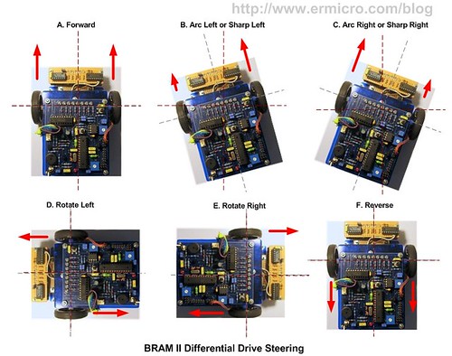
The BRAM DC motors are connected to the popular dual channel H-Bridge SGS-Thompson L293D chip; by feeding the right logic from the AVR ATMega168 PORT-D I/O (PD2,PD3,PD4 and PD7) to the 4 buffers inputs we could get the desired result:

The C function that control the BRAM II steering is BRAM_Steer(), which simply supply the right logic to the L293D chip input ports according to the truth table shown above:
// Define BRAM Steering
#define MOVE_FORWARD  0
#define TURN_LEFT     1
#define TURN_RIGHT    2
#define ROTATE_LEFT   3
#define ROTATE_RIGHT  4
#define MOVE_BACKWARD 5
#define FULL_STOP     6
...
...
void BRAM_Steer(unsigned char steer)
{
  switch(steer) {
    case MOVE_FORWARD:
	  PORTD &= ~(1 << PD4); PORTD |= (1 << PD7);  // Right Motor On Forward
	  PORTD &= ~(1 << PD2); PORTD |= (1 << PD3);  // Left Motor On Forward
      break;
    case TURN_LEFT:
  	  PORTD &= ~(1 << PD4); PORTD |= (1 << PD7);  // Right Motor On Forward
	  PORTD &= ~(1 << PD2); PORTD &= ~(1 << PD3); // Left Motor Off
      break;
    case TURN_RIGHT:
	  PORTD &= ~(1 << PD4); PORTD &= ~(1 << PD7); // Right Motor Off
	  PORTD &= ~(1 << PD2); PORTD |= (1 << PD3);  // Left Motor On Forward
      break;
    case ROTATE_LEFT:
 	  PORTD &= ~(1 << PD4); PORTD |= (1 << PD7);  // Right Motor On Forward
	  PORTD |= (1 << PD2); PORTD &= ~(1 << PD3);  // Left Motor On Reverse
      break;
    case ROTATE_RIGHT:
	  PORTD |= (1 << PD4); PORTD &= ~(1 << PD7);  // Right Motor On Reverse
	  PORTD &= ~(1 << PD2); PORTD |= (1 << PD3);  // Left Motor On Forward
      break;
    case MOVE_BACKWARD:
 	  PORTD |= (1 << PD4); PORTD &= ~(1 << PD7);  // Right Motor On Reverse
	  PORTD |= (1 << PD2); PORTD &= ~(1 << PD3);  // Left Motor On Reverse
      break;
    case FULL_STOP:
	  PORTD &= ~(1 << PD4); PORTD &= ~(1 << PD7);  // Right Motor Off
	  PORTD &= ~(1 << PD2); PORTD &= ~(1 << PD3);  // Left Motor Off
      break;
  }
}
The DC motor speed is controlled by supplying the PWM (Pulse Width Modulation) to L293D input enable ENABLE-1 and ENABLE-2 pins. In this design we use the AVR ATMega168 8-bit Timer/Counter0 PWM peripheral which give two independent PWM out on PD5 (OC0B) and PD6 (OC0A). For more information about using the PWM peripheral you could read my previous posted blogs Introduction to AVR Microcontroller Pulse Width Modulation (PWM) and Controlling Motor with AVR ATTiny13 PWM and ADC Project.
One of the important aspect when building a robot is to choose the precise PWM frequency for your DC motor as this could effecting your DC motor response to the PWM signal supplied to it. On this tutorial I apply 5400 Hz for the PWM frequency as it gives optimal response to the DC motor used on BRAM II. Following is the C code showing the AVR ATMega168 8-bit Timer/Counter0 PWM peripheral initialization:
// Initial The 8-bit Timer/Counter0 PWM
// Fast PWM Frequency = fclk / (N * 256), Where N is the prescaler
// f_PWM = 11059200 / (8 * 256) = 5400 Hz
TCCR0A = 0b10100011; // Fast PWM 8 Bit, Clear OCA0/OCB0 on Compare Match, Set on TOP
TCCR0B = 0b00000010; // Used 8 for the prescale
TCNT0 = 0;           // Reset TCNT0
OCR0A = 0;           // Initial the Output Compare register A & B
OCR0B = 0;
By varying the value assigned to the AVR ATMega168 microcontroller output compare register OCR0A and OCR0B we could varying the PWM signal from 0% to 100% (0 to 255). The C code that serve that purpose is the BRAM_DriveMotor() function which accept two arguments both for left and right DC motor speed. This function will also accept negative value arguments which are translated to the reverse DC motor rotation.
void BRAM_DriveMotor(int left_speed, int right_speed)
{
  unsigned char left_pwm,right_pwm;

  ...
  ...
  // Assigned the value to the PWM Output Compare Registers A and B
  OCR0A=right_pwm;
  OCR0B=left_pwm;
}
One last thing before you wire your DC motor power terminal to the L293D chip, is to find your DC motor power polarity where it give you the correct rotation direction base on the truth table shown above.
The Line Sensor Circuit
The line sensor is designed to takes advantage of the infra red reflective object sensor Junye JY209-01 or you could replace it with Fairchild QRE00034 to sense the black tape line; when the sensor is above the black tape line the infra red beam will not reflected back to the photo transistor and the photo transistor will turn off, if the sensor is on the white surface than the infra red beam will reflected back to the photo transistor and the photo transistor will turn on.

To make the sensor more sensitive and provide a smooth digital transition between “0” to “1” or vice verse; I use the NPN 2N3904 BJT to form the Darlington pair with the photo transistor to amplify the infra red signal received by the photo transistor, then feed the output (taken from the emitter) to the 74HC14 hex inverting Schmitt trigger chip. The infra red LED is controlled by NPN 2N3904 BJT through one of the 74HC14 inverting Schmitt trigger gate. For more information of using the transistor as switch you could read my previous blog Using Transistor as Switch.
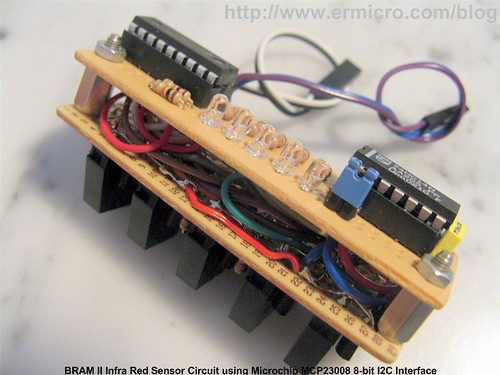
In order to lower the current taken from the MAX756 DC to DC Step-Up, two of the infra LED pairs are connected serially; this connection will produce about 3 x 20mA (60mA) instead of 5 x 20mA (100mA). I use the blue LED for displaying the sensor status as this type of LED need lesser current to produce decent light intensity compared to other LED. The reason why we have to carefully calculate the current needed, because all the electronic circuits and DC motors power is taken from the MAX756 chip which only capable to operate up to 200mA on 5 Volt output.

Finally the entire sensor output (IR0 to IR4) and input (CTRL) is connected to the Microchip MCP23008 I2C 8-bit I/O expander ports. The SCL and SDA pins connected directly to the AVR ATMega168 PORT-C PC5 (SCL) and PC4 (SDA) I2C bus pins.

As standard to all I2C devices; the MCP23008 has an unique 7 bits address consists of 4 bits device identification and 3 bits device physical address; the first 4 bits for MCP23008 device identification is “0100” and the last 3 bits of physical address is set to “111“, by connecting the A0, A1 and A2 pins to the 5 Volt.

The read and write C code to the MCP23008 chip is provided by the Read_MCP23008() and Write_MCP23008() functions respectively; these two functions used the MCP23008 I2C device protocol shown above to do this task. For more information of how to use the I2C devices please refer to my previous posted blog How to use I2C-bus on Atmel AVR Microcontroller.
Before we could use the MCP23008 I2C I/O expander, first we have to initialized the AVR ATMega168 microcontroller TWI (Two Wire Interfaces, Atmel own named for Philips I2C trademark) peripheral and assign the general purpose I/O GP0 to GP4 as the input port and GP5 to GP7 as the output port by writing to the MCP23008 IODIR register located on the address 0x00.
...
// Initial ATMega168 TWI/I2C Peripheral
TWSR = 0x00; // Select Prescaler of 1
// SCL frequency = 11059200 / (16 + 2 * 48 * 1) = 98.743 khz
TWBR = 0x30;         // 48 Decimal
// Initial the MCP23008 Devices GP0 to GP4 Input, GP5 to GP7 Output
Write_MCP23008(IODIR,0b00011111);
Write_MCP23008(GPIO,0b00111111);    // Reset all the Output Port, Make GP5 High
Write_MCP23008(GPPU,0b00011111);    // Enable Pull-Up on Input
...
Now you could read the reflective sensor status through the GP0 to GP4 port in the MCP23008 GPIO register. To reduce the current consumed by these infra red LED; we only turn on these infra red LED when we read the data by setting the GP5 to “0” when we read the sensor and toggling back to “1” after we get the sensor status. The sensor reading task is done inside the BRAM_IRSensor() function.
...
// Turn On the Sensor IR LED
Write_MCP23008(GPIO,0b00011111);

// Read sensor
sensor_val = Read_MCP23008(GPIO) & 0x1F;
// Turn Off the Sensor IR LED
Write_MCP23008(GPIO,0b00111111);
...
This function will also return the sensor value mapped according to the sensor_map array variable that is specifically designed to support our PID control algorithm.
// Define BRAM Variables
const unsigned int sensor_map[] PROGMEM = {
  0b00000,0,
  0b00001,10,
  0b00011,20,
  0b00010,30,
  0b00111,40,
  0b00110,50,
  0b00100,60,
  0b01100,70,
  0b11100,80,
  0b01000,90,
  0b11000,100,
  0b10000,110
};
If the black tape line is right at the center of all these five reflective sensors array, then the sensor circuit will return 0b00100, where the logical “1” means the third JY209-01 (connected to GP2) sensor position is right on the black tape line, while all the other sensors is on the white surface or logical “0“. This sensor’s value then will be mapped to the integer value 60 according to the sensor_map variable array above. This value later on will be used as our reference value (TARGET_VAL) for the PID control algorithm.

Now what happen if all of these sensors are out of the line, which mean the value returned by the sensor circuit will be 0b00000; the BRAM_IRSensor() function then will use it’s stored value (old_val variable) to determine whether the robot position is way out to the right of the line, it will return 0 or if the robot position is way out to the left of the line, it will return MAX_SENSOR_MAP (120). The following is the C code that serves that purpose:
// Define BRAM Sensor
#define MAX_MAP 24
#define TARGET_VAL 60
#define MAX_SENSOR_MAP 120
...
...
map_val=0;
// Adjust for zero result if previous value greater than TARGET_VAL
if (old_val > TARGET_VAL) map_val=MAX_SENSOR_MAP;
...
BRAM II Proportional, Integral and Derivative Control Algorithm
Now we come to the most interesting topics and yet it full of gray cloud and myth around it, especially for the robot builder. The proportional, integral and derivative control or PID for short actually is just one of the control methods that can be applied to the embedded system. The other popular controlling method includes the bang-bang and fuzzy logic is also widely used in the embedded system world.

From the diagram above you could see how I implement the PID control on the BRAM II Line Follower Robot. The BRAM_PIDControl() function get the reflective object sensor array output from the BRAM_IRSensor() function and calculate the required control response to steer correctly the BRAM II DC motors by supplying the required PWM value to the BRAM_DriveMotor() function.
The “Proportional Control” is used to fix the error produced by the line follower robot position toward the black tape line compared to reference value (TARGET_VAL) which represents the robot position is at the center of the line. Therefore we could write down the error function as this following formula:
ERROR = SENSOR_VALUE - TARGET_VALUE
The proportional control actually works similar to the gain (volume) control found at your stereo set where you could increase or decrease the music volume came out from the speaker, your ears act as the sensors which give you a feedback to your brain, while your target value is your preference music volume level. If the music volume level suddenly become higher compared to your preference level (error occur) than you decrease the volume level and vice verse. This gain factor usually called as the Kp (proportional) factor in PID control term. Therefore we could right down the control response as this following formula:
RESPONSE = Kp x ERROR
As mention before the BRAM_IRSensor() function will return the sensor map value from 0 to 120 where 0 mean our robot position is way out to the right while 120 mean our robot position is way out to the left; when BRAM_IRSensor() function return 60, mean our robot is right at the center of the line.
ERROR = SENSOR_VALUE - TARGET_VAL = 60 - 60 = 0
RESPONSE = Kp x ERROR = 0
If the response is 0 mean we could drive our robot to the maximum speed, so we could call the BRAM_DriveMotor() function as follow:
BRAM_DriveMotor(Left_Max_PWM, Right_Max_PWM);
When BRAM_IRSensor() function return 0
ERROR = SENSOR_VALUE - TARGET_VAL = 0 - 60 = -60
RESPONSE = Kp x ERROR = - 60 Kp
The negative response mean we have to turn or arc to the left to make the correction, this could be done by reducing the left motor PWM value (reducing left motor speed), while keep the right motor PWM value on it maximum value.
BRAM_DriveMotor(Left_Max_PWM + RESPONSE, Right_Max_PWM);
When BRAM_IRSensor() function return 120
ERROR = SENSOR_VALUE - TARGET_VAL = 120 - 60 = 60
RESPONSE = Kp x ERROR = 60 Kp
The positive response mean we have to turn or arc to the right to make the correction, this could be done by reducing the right motor PWM value (reducing right motor speed), while keep the left motor PWM value on it maximum value.
BRAM_DriveMotor(Left_Max_PWM, Right_Max_PWM - RESPONSE);
The Kp constant value could be any number that will boost the response value, following is the C code part of the BRAM_PIDControl() function that implements the explanation above:
...
...
// Negative result mean BRAM is on the right, so we need to adjust to the left
// Positive result mean BRAM is on the left, so we need to adjust to the right
if (motor_res < 0)
  BRAM_DriveMotor(MaxSpeed + motor_res,MaxSpeed); // Left less speed, Right full speed
else
  BRAM_DriveMotor(MaxSpeed,MaxSpeed - motor_res); // Left full speed, Right less speed
Using just the “Proportional Control” alone will resulting the zigzag steering behavior of the robot, therefore we have to combine it with “Integral Control” or “Derivative Control” or both of them to produce more accurate and stable robot’s steering movement. The following is the industrial standard PID control mathematic formula:

The “Integral Control” is used to reduce the accumulated error produced by the proportional control over the time or it’s also called a steady-state error, therefore the longer the robot produces an error (not in the center of the black line) the higher the integral control response output value.
The “Derivative Control” is used to speed up the proportional control error response, therefore the faster the robot produce an error such as zigzag steering movement the higher the derivative control response output value. In other word the derivative control will help to reduce the zigzag steering behavior of the robot.
Now as you understand the PID concept it’s time to convert or transform the PID formula above to the form that could be applied directly to the AVR ATMega168 microcontroller. For the purpose of this tutorial I will not describe of how we discretization this mathematic formula using the trapezoidal rule, the following is the complete PID control formula taken from the Thomas Braunl, Embedded Robotics, Second Edition Springer-Verlag 2006:

The following is the BRAM II Line Follower Robot C code that implements the PID control formula shown above:
...
unsigned char MaxSpeed;                         // Hold Motor Maximum Speed
unsigned int Kp,Ki,Kd;                          // PID Parameters
int prev_res=0, prev_err_1=0, prev_err_2=0;     // PID Control Variables
...
...
int motor_res,err_func;
float KP,KI,KD,cont_res;
// Get the Error Function
err_func=sensor_val - TARGET_VAL;
// Divide all the PID parameters for decimal value
KP=Kp * 0.1;
KI=Ki * 0.01;
KD=Kd * 0.01;
// Calculate the Motor Response using PID Control Equation
cont_res=(float)(prev_res + KP * (err_func - prev_err_1) + KI * (err_func + prev_err_1)/2.0
               + KD * (err_func - 2.0 * prev_err_1 + prev_err_2));

// Now we have to Limit the control response to the Maximum of our motor PWM Motor Value
motor_res=(int)cont_res;
if (motor_res > MaxSpeed)
  motor_res = MaxSpeed;
if (motor_res < -MaxSpeed)
  motor_res = -MaxSpeed;
// Save the Motor Response and Error Function Result
prev_res=motor_res;
prev_err_2=prev_err_1;
prev_err_1=err_func;
Once you run the program you could tune the PID control parameter by entering BRAM II setup mode (pressing the AVRJazz Mega168 board user switch twice) and connecting the AVRJazz Mega168 RS232 port to your computer terminal program such as Windows HyperTerminal or puTTY using these following guide lines:
- Turn off all the Integral and Derivative control by zeroing the Ki and Kd parameters
- Slowly increase the Proportional parameter (Kd) by the factor of ten (i.e. 10, 20, 30,…) and watch the robot behavior, if the robot tend to oscillate (zigzag) decrease this parameter
- Slowly increase the Integral parameter (Ki) by the factor of one (i.e. 1, 2, 3,…) again watch the robot behavior until it nearly oscillate
- Slowly increase the Derivative parameter (Kd) by the factor of one (i.e. 1, 2, 3,…) again watch the robot behavior until it become stable
- You have to repeat these whole processes for different speed setting. Remember there are no such exact values for the PID parameter; the PID parameter depends heavily on your motor and sensor characteristic.

Inside the C Code
The program start by initializing the ATmega168 ports, than we continue with the UART peripheral, 8-bit Timer/Counter0 PWM peripheral, TWI peripheral and finally the ADC peripheral that is used to set the maximum speed of the DC Motors. Again most of the functions used in this project are based on my previous posted blogs mention above.
The UART Functions:
- The UART functions are used to handle the communication with the PC:
- uart_init() function is used to initialize the ATMega168 UART peripheral
- uart_flush() function is used to empty the ATMega168 UART data register
- uart_putch() function is used to put single character to the UART port
- uart_getch() function is used to read single character from the UART port
- ansi_cl() function is used to clear the ANSI emulation terminal screen
- ansi_me() function is used to turn off all attribute on the ANSI terminal emulation
- ansi_cm() function is used to move cursor on the ANSI terminal emulation
- get_num() function is used to validate the user input; this function used the standard I/O C function scanf() to read the user input from the HyperTerminal or puTTY program
The application standard input and output stream is being redirected to both UART input and output with theses statements bellow:
// Assign I/O stream to UART
FILE uart_str = FDEV_SETUP_STREAM(uart_putch, uart_getch, _FDEV_SETUP_RW);
...
// Define Output/Input Stream
stdout = stdin = &uart_str;
The BRAM II Motor Functions:
The BRAM II motor functions are used to control the BRAM II motor steering and speed:
- BRAM_Steer() function is used as the basic function to control the DC motor steer where it supply correct logic to the L293D chip
- BRAM_DriveMotor() function is used to control the BRAM II steer and speed
- BRAM_PIDControl() function is the BRAM II implementation of Porportional, Integral and Derivative control
The MCP23008 I2C Functions:
The I2C functions are used to perform reading and writing to the I2C devices:
- i2c_transmit() function is used to transmit data to the I2C devices and wait for transmission done by monitoring the interrupt flag bit (TWINT) to be set.
- i2c_start() function is used to send the I2C start condition
- i2c_stop() function is used to send the I2C stop condition
- i2c_write() function is used to write data to the I2C slave device register
- i2c_read() function is used to read data from the I2C slave device register
- Write_MCP23008() function is used to send data to the MCP23008 register
- Read_MCP23008() function is used to read data from the MCP23008 register
Inside the infinite loop
BRAM II used the AVRJazz Mega168 board user potentiometer connected to the AVR ATMega168 microcontroller PC0 (ADC0) pin to determine the BRAM II maximum speed. The ADC value read from this port will be used as the maximum PWM value for controlling the motor’s speed. Because we use 8-bit PWM value, therefore we only need 8-bit ADC precision from the 10-bit ADC precision provided by the AVR ATMega168 ADC peripheral. This following C code showing the ADC peripheral initiation where we use the right justified for the ADC result taken from the ADCH register. For more information of working with ADC peripheral you could read my previous posted blog Analog to Digital Converter AVR C Programming.
...
// Set ADCSRA Register on ATMega168
ADCSRA = (1<<ADEN) | (1<<ADPS2) | (1<<ADPS1);
// Set ADMUX Register on ATMega168
ADMUX = (1<<ADLAR); // Use Right Justified, Select Channel 0
...
...
// Start conversion by setting ADSC on ADCSRA Register
ADCSRA |= (1<<ADSC);
// wait until convertion  complete ADSC=0 -> Complete
while (ADCSRA & (1<<ADSC));
// Get ADC the Result
MaxSpeed = ADCH;
Inside the for-loop (infinite loop) we simply read the AVRJazz Mega168 on board user switch (connected to AVR ATMega168 PB0 pin) and if pressed then we will run the BRAM II (mode 1) and if pressed twice (mode 2) we will enter the BRAM II parameter setup using Windows HyperTerminal or puTTY program and later on store this setup on the AVR ATMega168 microcontroller EEPROM.
...
// Write the Kp,Ki and Kd to EEPROM Address: 0x0000,0x0002,0x0004
eeprom_write_word((unsigned int*) 0x0000,Kp);
eeprom_write_word((unsigned int*) 0x0002,Ki);
eeprom_write_word((unsigned int*) 0x0004,Kd);
The stored PID control parameter later on will be read back from the EEPROM by the Read_Parameter() function every time we power on the BRAM II.
void Read_Parameter(void)
{
  // Read the Kp,Ki and Kd From EEPROM at Address: 0x00,0x02,0x04
  Kp=eeprom_read_word((unsigned int*) 0x0000);
  Ki=eeprom_read_word((unsigned int*) 0x0002);
  Kd=eeprom_read_word((unsigned int*) 0x0004);
}
Compile and Download the Code to the board
Before compiling the code, we have to make sure the AVR Studio 4.17 configuration is set properly by selecting menu project -> Configuration Option, the Configuration windows will appear as follow:

Make sure the Device selected is atmega168 and the Frequency use is 11059200 hz and because we use float number calculation, you should include the link to AVR-GCC libm.a library object in your libraries option to reduce the program size.


After compiling and simulating our code we are ready to down load the code using the AVRJazz Mega168 bootloader facility. The bootloader program is activated by pressing the user switch and reset switch at the same time; after releasing both switches, the 8 blue LED indicator will show that the bootloader program is activate and ready to received command from Atmel AVR Studio v4.17 STK500 program.

We choose the HEX file and press the Program Button to down load the code into the AVRJazz Mega168 board. Now it’s time to relax and enjoy your hard work by watching BRAM II Line Follower Robot in action:
The Final Thought
As you’ve learned from this BRAM II Line Follower Robot tutorial, to design and build the microcontroller based robot successfully, you need to use many of the microcontroller supported peripheral features (e.g. I/O, PWM, UART, ADC, TWI) at the same time, therefore having a good and solid understanding of how these peripheral work will help you solve most of the problem occur when building the microcontroller based robot.
Bookmarks and Share


Related Posts
42 Responses to “Build Your Own Microcontroller Based PID Control Line Follower Robot (LFR) – Second Part”
Comment by rwb.
Hi Naveen, The ADC is used to control the maximum motor speed by reading the user trimport (AVRJazz Mega168 board) connected to the PC0 (it should be PC0 not PC5, corrected) or ADC0. The 8-bit ADC value (ADCH) than will be assigned to the PWM control variable (MaxSpeed), which is used in the BRAM_PIDControl() function. You could read more about AVRJazz Mega168 board on “AVRJazz Mega168 Learning and Development Board” (http://www.ermicro.com/blog/?p=1)
Comment by kakashi594.
How much does it cost,please?
Comment by rwb.
The AVRJazz Mega168 board is about USD 50, The IR sensor circuit is about USD 20, Motor Drive and Step Up circuit is about USD 10, The DC Geared Motor + Wheel is about USD 25, Robot Chassis, accessories and 3xAA Battery holder + Battery is about USD 5. Therefore the total Cost is about USD 110.
Comment by kakashi594.
could you provide us with the layout of the circuits,please?
Comment by rwb.
All the circuit schematic, i.e. motor driver, sensors, and DC Step Up is already provided here. You could fine the AVRJazz Mega168 board circuit schematic in “AVRJazz Mega168/328 Learning and Development Board” article.
Comment by kakashi594.
I know it seems dumb but I really new in the field.Why don’t we use one microcontroller for the sensor and power circuits?.and what’s the jp symbol in the circuits above. Will it be alright if I use pic microcontroller or the avr is a must?
Comment by rwb.
For the LFR, you don’t need to use one microcontroller for a sensor nor for the power. The JP symbol in the circuit schematic is stand for “Jumper”. Sure you could use PIC microcontroller, which mean you need to make a lot of adjustment in the circuit schematic and programming. I simply use the Atmel AVR microcontroller because this LFR article is the first Atmel AVR microcontroller based robotics project that I posted on this blog; previously I’ve post the Microchip PIC microcontroller based robotics project on “Building BRAM your first Autonomous Mobile Robot using Microchip PIC Microcontroller – Part 1” and “Behavior Based Artificial Intelligent Mobile Robot with Sharp GP2D120 Distance Measuring Sensor – BRAM Part 2” articles. Therefore I hope the readers of this blog could learn to use both of these microcontrollers (i.e. AVR and PIC) in the robotics project.
Comment by pichaha.
Hi,
I have some questions here regarding to the PID control…
Actually I have a project with me now, it is a PID controller for X-Y positioning table…
I would like to ask, is the PID concept and equation identical to the measurement of any physical quantity??
I mean can the same PID equation be used to measure any physical quantity, such as position, speed, and others??
Besides, I am going to use DC motor as my actuator and potentiometer as the sensory device in my project…can you recommend any high quality and high resolution dc motor and potentiometer…Is it appropriate to use dc motor to drive X-Y table…
Hope to hear from you soon, thanks a lot.
Comment by pichaha.
Hi, thanks for the reply…
I would like to ask is it possible to control X-Y table using microcontroller?? Thanks.
Comment by rwb.
Basically the PID system is depend on the feedback from the controlled entities, therefore by providing an adequate feedback from the position and speeds, you could use the PID principal for the error correction.
Yes you could use the DC motor and potentiometer (a feedback system) to drive the X-Y table (e.g. Gantry Crane) and its easier to use a microcontroller to drive the DC motors in X-Y coordinate.
Comment by pichaha.
Hi thanks for the reply…
Can you please advice whether there are anything that need to be concerned when selecting DC motor and potentiometer? I want to buy two high precision dc motor and potentiometer…I am planning to buy the things online…do you know any useful website??
Thanks a lot.
Comment by rwb.
I think the most important is that you could get the technical specification (datasheet) for both the DC motor and potentiometer. For the website, currently I don’t have any referral for your needs.
Comment by pichaha.
Hi, never mind, anyway thanks a lot…
Comment by pichaha.
Oh ya, I got a question here…I would like to ask, by using microcontroller it is impossible to control xy table in continuous manner right?? I mean we can specify and locate the position of the xy table by using microcnotroller and reset it to specify another location, but we can’t make it move in circular or any nonlinear way right??
Thanks a lot…
Comment by pichaha.
Hi, I am sorry, it is me again, haha…
I have just unintentionally read your recommended link (Learn PID control) from this article and I found that I am extremely interested with that…now I am planning to buy the <>, but before I purchase I would like to ask for your guide and suggestion.
From those feedbacks in the link, I can expect that this book will be definitely useful. But I would like to ask will I need the knowledge from the book currently for my PID controller XY table project? I will need to tune the PID parameters in my project, but I am afraid the thing that I am doing might be too elementary comparing to the application in industrial plant, hence the book might be too deep for me currently.
p/s: Currently I am a degree student.
Please advice, thanks a lot.
Comment by rwb.
First the PID system actually depend on the continuously feedback as shown on the LFR project where the IR sensor continuously feeds the black line position to the microcontroller as the LFR move on the track. Secondly about the “Thomas Braunl, Embedded Robotics book”, this book actually is aimed for an introductory course in robotics for the EE students.
Comment by pichaha.
Hi,
I am sorry the book I meant is “PID Tuning Blueprint” from Finn Peacock…thanks
Comment by nomad91.
hey man awesome info..but I’ve got a doubt what about tuning the Ir sensor ?..many other circuit I’ve seen use a pot or variable resister to calibrate or tune the Ir sensor circuit as per the condition..
Comment by rwb.
The infrared (IR) sensor used in this project use different approach compare to many other LFR IR sensor (i.e. connected to microcontroller ADC peripheral). The IR sensor simply supply the ON/OFF condition using the Schmitt trigger chip (74HC14) to the microcontroller digital input, which is no need to be calibrated.
Comment by pichaha.
Hi,
Is the “PID Tuning Blueprint” suitable???
Please advice, thank you very much.
Comment by rwb.
I’ve never read that book, basically any PID books is good for references especially if it give you a real example not just a mathematics equation.
Comment by pichaha.
Hi, I would like to ask, do you impement system modeling and PID controller design by simulation first before you tranfer it into c codes then to microcontroller, or you use trial and error method to get the PID parameters??
Comment by pichaha.
Thanks.
Comment by rwb.
For the Line Follower Robot project, it’s easier to use the trial and error method to tune the PID parameters as described in the above article of how to tune the LFR PID parameters using the serial terminal.
Comment by thujeevan.
first, thanks for very nice article.
i want to use ldr and led for sensor array instead of ir,
then what are the modifications would be needed in the programming part and hardware part to achieve this?
Comment by rwb.
In the hardware part you have two options, the first is to use simply voltage divider and give analog output, the second approach is to use the interface circuit (e.g. transistor) to convert the LDR output to the logical output. In the programming part is depend on your hardware implementation choices, where you just need to adjust the BRAM_IRSensor() function to read the LDR sensor.
Comment by thujeevan.
thanks for your reply,
what i want to know is, generally what is the purpose of 74HC14 hex inverting Schmitt trigger chip, and here which is the specific purpose?
assume that i am using LDR without any interface circuit,
how it will affect the output of 74hc14 and i2c output?
Comment by rwb.
The schmitt Trigger (74HC14) is used as the signal recondition so the transition from logical “0” to “1” or vise versa will be smooth. If you replace the IR sensor with LDR you need to experiment with it, basically each of the IR sensors will supply a logical input to the Microchip MCP23008 I2C I/O expander.
Comment by perla.
I want to ask what’s you mean about the black tap sensor? and where can i found it?
please, answer this quastion. I need it.
Comment by perla.
I am talking about black bar followed by the car
Is it just Paint black or a specific material?
because i know that this type of sensor can’t see the diferent among colors, but i think that some colors refected light less than another types.
thank you
Comment by Cereb.
hi…many thanks for this awsum tutorial…..i just want to ask 1 thing that is …i hav to build this LFR for white line on black surface…. what necessary alterations do i hav to do in the whole process of LFR making……Thanks
Comment by rwb.
You just need to change the program, for example the original sensor_map center value of 0b00100 (mapped to 60) could be changed to 0b11011 when using a white line over the black background.
Comment by Cereb.
thank you so much…. i i wnat to ask you hav used resistors in the sensing circuit what will be the values of the resistors in the sensing circuit………..
Comment by rwb.
The resistors value is shown on the schematic above (i.e. BRAM II InfraRed Sensor Circuit).
Comment by munirnizami.
hello
i have made your transistor lfr , its working properly but the transistors are getting very hot very fast. i have used normal dc toy motors and its working properly. i couldnt find any dc gear motors so i used toy motors. now what should i do to transistors to remain them cold? should i use heat sink or what ?? please reply fast
thankyou
Comment by rwb.
You could not use a toy motor for the project as it designed to use low current DC geared motor.
Comment by firebolt.
I am implementing a temperature control system and for that I need to implement a PID control. Please guide me what to do and what changes to your code would work for my project? I am basically setting a reference temperature and then trying to maintain the system at that temperature using feedback from a sensor.
Comment by LittleBoy.
Hi, can I ask you a question ? Where can I buy AVRJazz Mega168 board ? Because I need it for my Final-year-project.If possible, can you give me the website, so I can purchase it immediately. Pls reply ASAP

Comment by naveen.
firstly thank you for the useful information provided.
could u please explain more about the functionality the adc in the loop. and from where is the input to the adc provide.