Blog Entry
Introduction to AVR Microcontroller Pulse Width Modulation (PWM)
December 5, 2008 by rwb, under Microcontroller.
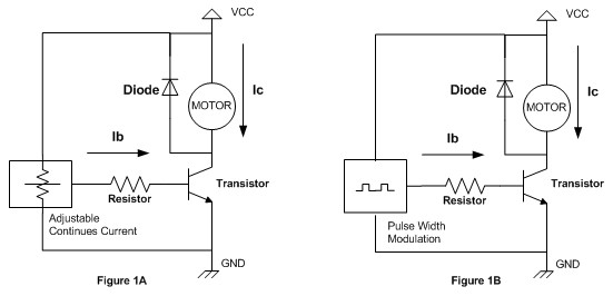
PWM is used in many industrial mostly for controlling the motor speed. The PWM is used because it’s the most efficient method comparing to the analog one. That’s why most of the modern microcontrollers today have this features build in. How does this PWM works will be described on the following circuits:
On the figure 1A the motor is controlled by applying continues current through transistor base lead and this will cause the continues current flow through transistor’s collector lead by the factor of transistor’s gain (Ic = gain x Ib); the more current we put on the transistor’s base lead the more current Ic will flow through the transistor’s collector lead; this also mean the motor speed is depend on the current we put on transistor’s base lead. Using this kind of method, make the transistor always in the working stage and as a result the power dissipation (power lost as heat) on the transistor become very high.
On the other circuit figure 1B the motor is controlled by applying pulse current through the transistor’s base lead and this will cause the Ic pulse current flow through transistor’s collector lead. By varying the pulse width and using the right frequency, we could control the motor speed. Using the pulse current make the transistor on and off very quickly, this will reduce much of the power dissipation on the transistor. This kind of method is known as pulse width modulation or PWM for short.
The disadvantage of using the PWM method is the electronics circuit to produce this signal tend to be complex, but thanks to today’s technology; even the most cheapest and tiny microcontroller such as AVR Tiny13 (only have 8 pins) could produce this PWM easily. For the purpose of this tutorial I will use Atmel AVR Tiny2313 microcontroller for playing with the PWM, but you could apply the principal to almost all AVR microcontroller family.
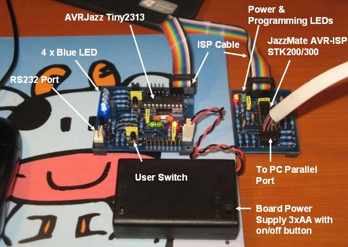
The following is the list of hardware and software I use in this tutorial:
- AVRJazz Tiny2313 learning board from ermicro
- JazzMate AVR-ISP STK200/300 programmer board from ermicro
- WinAVR for the GNU’s C compiler
- Atmel AVR Studio 4 for the coding, compiling and debugging environment
- Kanda AVRISP STK200/300 for the programmer software; nicely plug in to the Atmel AVR Studio 4.14
The AVRJazz Tiny2313 has four LEDs attached to the PORT B0 through PORT B3 and we will use the LED on PORT B3 for outputting the PWM signal. Ok let’s start the coding now !
//************************************************************************
//  File Name     : pwmintro.c
//  Version       : 1.0
//  Description.  : Introduction to AVR microcontroller PWM
//                : Fast PWM Mode (8 Bit)
//  Author(s)     : RWB
//  Target(s)     : AVRJazz Tiny2313 Board
//  Compiler      : AVR-GCC 4.3.0; avr-libc 1.6.2 (WinAVR 20080610)
//  IDE           : Atmel AVR Studio 4.14
//  Programmer    : Kanda STK200/300 ver 5.0.0.324
//                : JazzMate AVR-ISP STK200/300
//************************************************************************
#include <avr/io.h>
#include <util/delay.h>
int main(void) {
  int ipwm;
  // Initial Port I/O
  DDRB=0xFF;           // Set PORTB as Output
  // Initial PWM
  TCCR0A = 0b10000011; // Fast PWM 8 Bit
  TCCR0B = 0b00000001; // No Prescaler
  TCNT0 = 0;           // Reset TCNT0
  for(;;) {            // Loop Forever
    ipwm=0;
    while (ipwm <= 255) {
      OCR0A=ipwm++;
      _delay_ms(2);    // Delay 2 millisecond
    }
    ipwm=255;
    while (ipwm >= 0) {
      OCR0A=ipwm--;
      _delay_ms(2);    // Delay 2 millisecond
    }
    _delay_ms(100);    // Delay 100 millisecond
  }
  return 0;            // Standard Return Code
}
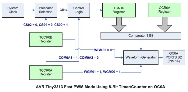
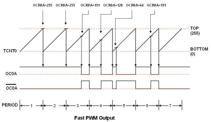
The first statement is to instruct the microcontroller to enable the output for PORTB, this can be achieved by setting all the port B data direction register DDRB to 0xFF (0b11111111). Now the next two statements is to enable the AVR ATTiny2313 microcontroller for 8 bit Fast PWM mode; the following diagram is a simple version of how the PWM is generated in AVR ATTiny2313 microcontroller (for the complete PWM diagram version please refer to the datasheet):
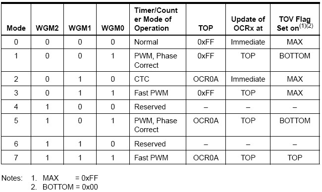
From the diagram above the PWM setting is in the two timer counter registers TCCR0A and TCCR0B. We choose the Fast PWM mode by assigning the WGM02 = 0 bit in TCCR0B register and WGM01 = 1, WGM00 = 1 bits in TCCR0A register.
The TCNT0 register is where the actual counter run; it starts from 0 and count up to 255 and back to 0 again. The counting speed in TCNT0 register is depends on the system clock and the prescale factor we choose.
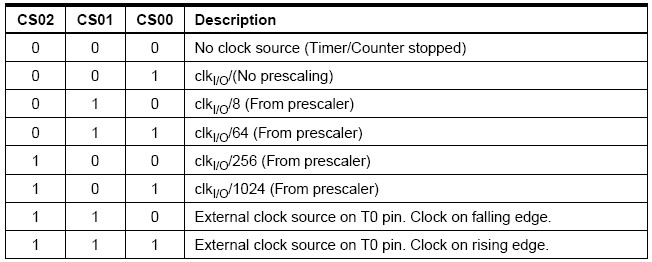
For example if we have the system clock of 11059200 Hz and we use 1024 as the prescale factor (CS02=1, CS01=0, CS00=1) then the TCNT0 register will count every 1 / (11059200/1024) second or 0.0925 millisecond. On this tutorial we use prescale factor of 1 (CS02=0, CS01=0 and CS00=1).
Every time TCNT0 register value equal to OCR0A register value then the comparator will signal the waveform generator to clear the OC0A output; but every time the TCNT0 register value reach TOP (i.e. 255) then the waveform generator will set the OC0A output.
From the diagram above we could see how this PWM output is formed by the waveform generator base on value of the OCR0A register. Therefore by varying the OCR0A register value we could varying the width of the pulse; that it’s why is called pulse width modulation. We use this Fast PWM mode because the period of this pulse generated by the waveform generator is constant; what varied only the pulse width. The frequency generated can be calculated using this following formula:
Where N is the prescale factor; therefore using this formula, the frequency use in this tutorial is:
N=1, system clock = 11059200 Hz
Frequency output = 11059200 / 256 = 43200 Hz.
This frequency is above the human hearing threshold which is 20000 Hz. Usually for controlling the high efficient DC motor such as walkman’s cassette motor we could use the PWM frequency above 20000 Hz but for low efficient motor such as children’s toy motor we use frequency below 100 Hz; but again you could experiment with it by changing the precale factor and see the result.
By changing the COM0A1=1 and COM0A2=1 on the TCCR0A register we could toggle the OC0A output; on this tutorial we use COM0A1=1 and COM0A0=0.
From here you could learn how easy to create the PWM using the microcontroller; first we set the microcontroller in Fast PWM mode by setting the TCCR0A and TCCR0B registers than second we just changing the value of OCR0A register from 0 to 255. Referring to the code example above; we simply use the PWM for dimming the LED from dark to bright and to dark again using two while loop statement; of course you could change the LED with DC motor by using a proper interface; on my next tutorial I will show how to interface the DC motor using the transistors.
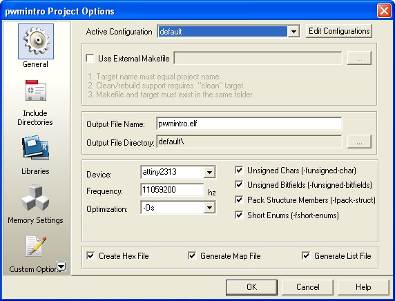
Ok let’s down load the hex code to the board now; first we set the board frequency 11059200 Hz in the AVR Studio 4 configuration by selecting menu Project -> Configuration option as follow:
Then we compile and build the Hex file by selecting the menu Build -> Build or press F7; after success compiling the code than select menu Tools -> KandaTools -> AVRISP for downloading the Hex code using JazzMate AVR-ISP STK200/300 board as follow:
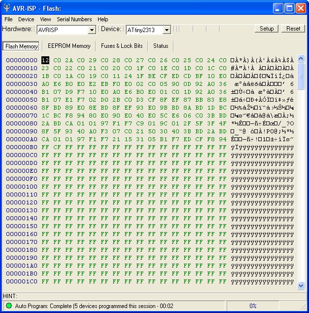
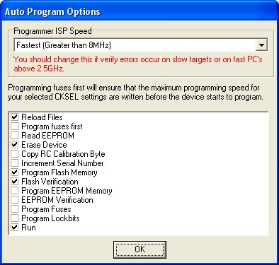
Load your Hex code file into the programmer by selecting menu File -> Load and chose your Hex file. Adjust the auto programming facility if necessary by selecting menu Device -> Auto Program Option as follow:
Then you are ready to download the code by selecting menu Device -> Auto Program or Press F5. Now you could see the PWM code working on the AVRJazz Tiny2313 board in the following video:
For those who want the similar code in AVR assembler or just as a reference of how to code this PWM introduction tutorial in AVR assembler you could use this following code:
;************************************************************************
;  File Name	  : asmpwmintro.asm
;  Version	  : 1.0
;  Description.   : Introduction to AVR microcontroller PWM
;                 : Fast PWM Mode (8 Bit)
;  Author(s)      : RWB
;  Target(s)	  : AVRJazz Tiny2313 Board
;  Compiler/IDE   : Atmel AVR Studio 4.14
;  Programmer     : Kanda STK200/300 ver 5.0.0.324
;                 : JazzMate AVR-ISP STK200/300
;************************************************************************
.include "tn2313def.inc"
; The AVRJazz Tiny2313 Board Frequency Clock
.equ F_CPU = 11059200
.cseg
; Start on the flash ram's address 0
.org 0
main:   ldi R24,RAMEND         ; Initial Stack Pointer
        out SPL,R24            ; SP = RAMEND
; Initial I/O
        ldi   R16,0xFF
        out   DDRB,R16         ; DDRB=0xFF
; Initial PWM
        ldi   R16,0b10000011
        out   TCCR0A,R16       ; TCCR0A = 0b10000011
	ldi   R16,0b00000001
	out   TCCR0B,R16       ; TCCR0B = 0b00000001
repeat: ldi   R16,255          ; R16 = 255
bright: inc   R16              ; R16 = R16 + 1
        out   OCR0A,R16        ; OCR0A = R16
	ldi   R19,1
	rcall delay_func       ; Call Delay Function Parameter R19 = 1
        cpi   R16,255
	brne  bright           ; if (R16 != 255) goto bright label
	out   OCR0A,R16        ; OCR0A = R16
	ldi   R19,1
	rcall delay_func       ; Call Delay Function Parameter R19 = 1
	clr   R16              ; R16 = 0
dark:   dec   R16              ; R16 = R16 - 1
        out   OCR0A,R16        ; OCR0A = R16
	ldi   R19,1
	rcall delay_func       ; Call Delay Function Parameter R19 = 1
        cpi   R16,0
	brne  dark             ; if (R16 != 0) goto dark label
	out   OCR0A,R16        ; OCR0A = R16
	ldi   R19,50
	rcall delay_func       ; Call Delay Function Parameter R19 = 50
	rjmp  repeat

; Simple Delay Function
delay_func:
delay0: ldi   R20,25           ; R20 = 25
delay1: ldi   R21,255          ; R21 = 255
delay2: dec   R21              ; R21 = R21 - 1
	brne  delay2           ; if (R20 != 0) goto delay2 label
        dec   R20              ; R20 = R20 - 1
        brne  delay1           ; if (R20 != 0) goto delay1 label
	dec   R19              ; R19 = R19 - 1
        brne  delay0           ; if (R19 != 0) goto delay0 label
	ret                    ; Return to the caller
.exit
Bookmarks and Share


