Blog Entry
AVR Twinkle Twinkle Using PWM Project
January 10, 2009 by rwb, under Microcontroller.
Would be interesting if we could make our microcontroller to sing for us not just beeping or blinking; this project is all about using the powerful AVR ATmega168 16-bit PWM feature to produce accurate musical notes such as playing the child’s favorite Twinkle-Twinkle Little Star song or we could say beeping with style. The principal we learned here could be applied to other AVR microcontroller families that support 16-bit PWM.
Basic natural sound we usually hear is formed by fast vibration; this vibration can be produced by many sources such as by string like guitar, piano, violin or by our vocal membrane when we sing or talk. All this sound produced the sound wave known as sine or sinusoid wave. By using the same principal we could produce sound electronically using oscillator circuit; this circuit basically is the amplifier with the input signal taken from the output or known as feedback. By amplifying this feedback signal over and over the amplifier become unstable and starts to oscillate; the output of this signal will be feed to the speaker and the speaker will vibrate according to the sound wave frequency.
This behavior can be observed when we talk on the microphone and if the microphone is close enough to the speaker suddenly we will hear the sound coming out from the speaker and usually we call it as the feedback sound.

In the digital circuit we could create such vibration by using the same feedback principal; but the waveform generated by the digital circuit is a square waveform, therefore we have to change the waveform to the waveform normally produced by nature or the sine waveform. Normally we will use the integrator circuit or known as low pass filter to change the square waveform to the triangle waveform and another low pass filter to change this triangle waveform to the sine waveform.
The explanation of how it works required complex mathematical equations; but we could express it in practical terms that the square wave signal actually is a combination of the fundamental sine wave frequency plus all the odds sine wave harmonic frequencies at diminishing amplitude. This statement is known as a Fourier’s theory. For example if we have a square wave signal with frequency of 1 kHz, according to the Fourier’s theory we could represent this signal as a sum of all series of sine wave signals start from 1 kHz (the fundamental), 3 kHz (third harmonic), 5 kHz (fifth harmonic), 7 kHz (seventh harmonic), 9 kHz (ninth harmonic) and so on.
Therefore by passing the fundamental frequency and filtering all the harmonic frequencies using the low pass filter, we could get the fundamental sine wave signal. Another dirty method is to feed directly the square wave output to the speaker or piezoelectric material which works as the low pass filter; this is the method we used in this project. By using the sophisticated AVR PWM peripheral it’s easy for us to generate this square wave signal.
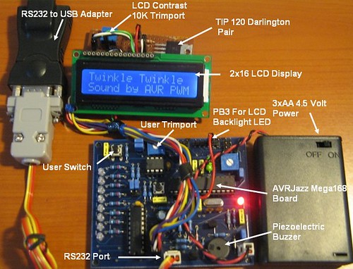
The following is the list of hardware and software we will use in this project:
- 1 4K7 Resistor
- 1 TIP120 Darlington pair transistor
- 2×16 LCD with back light LED
- 10 K Trimpot
- AVRJazz Mega168 board from ermicro which base on the AVR ATmega168 microcontroller (board schema).
- WinAVR for the GNU’s C compiler
- Atmel AVR Studio 4 for the coding and debugging environment
- STK500 programmer from AVR Studio 4, using the AVRJazz Mega168 board STK500 v2.0 bootloader facility

The TIP 120 (you could change it with BC639 or it equivalent) is used for powering the LCD back light LED which is controlled by the PB3 output port from ATmega168 microcontroller. With this design we could easily enable the LCD back light LED or disable it as the back light LED consume a lot of power (about 100mA), in this project we will use the PWM signal to control this LCD back light LED.

Now let’s take a look at the C code that make this happen.
//***************************************************************************
//  File Name    : basicsound.c
//  Version      : 1.0
//  Description  : Basic AVR Sound with PWM
//  Author(s)    : RWB
//  Target(s)    : AVRJazz Mega168 Learning Board
//  Compiler     : AVR-GCC 4.3.0; avr-libc 1.6.2 (WinAVR 20080610)
//  IDE          : Atmel AVR Studio 4.14
//  Programmer   : AVRJazz Mega168 STK500 v2.0 Bootloader
//               : AVR Visual Studio 4.14, STK500 programmer
//  Last Updated : 02 Jan 2008
//***************************************************************************
#include <avr/io.h>
#include <util/delay.h>
// The Frequency is taken from http://www.phy.mtu.edu/~suits/notefreqs.html
#define C6  661
#define D6  588
#define E6  524
#define F6  495
#define G6  441
#define A6  393
#define B6  350
#define C7  330
#define PAUSE 80
#define LCD_HOME 0x02
#define LCD_NEXT_LINE 0xC0
#define LCD_CLEAR 0x01
#define LCD_1CYCLE 0
#define LCD_2CYCLE 1
void LCD_putch(unsigned char data)
{
  // LCD Upper 4 bits data (DB7,DB6,DB5,DB4)
  PORTD = (1<<PD3)|(1<<PD2)|(data & 0xF0);        // RS = 1, E = 1
  // E=0; write data
  PORTD &= ~(1<<PD3);
  _delay_us(1);

  // LCD Lower 4 bits data (DB3,DB2,DB1,DB0)
  PORTD = (1<<PD3)|(1<<PD2)|((data & 0x0F) << 4); // RS = 1, E = 1

  // E=0; write data
  PORTD &= ~(1<<PD3);
  _delay_ms(5);     // Wait for busy flag (BF)
}
void LCD_putcmd(unsigned char data,unsigned char cmdtype)
{
  // LCD Upper 4 bits data (DB7,DB6,DB5,DB4)
  PORTD = (1<<PD3)|(data & 0xF0);                 // RS = 0, E = 1
  // E=0; write data
  PORTD &= ~(1<<PD3);
  _delay_us(1);

  // cmdtype = 0; One cycle write, cmdtype = 1; Two cycle writes
  if (cmdtype) {
    // LCD Lower 4 bits data (DB3,DB2,DB1,DB0)
    PORTD = (1<<PD3)|((data & 0x0F) << 4);        // RS = 0, E = 1

    // E=0; write data
    PORTD &= ~(1<<PD3);
  }
  _delay_ms(5);    // Wait for busy flag (BF)
}
void initlcd()
{
  // Wait for more than 15 ms after VCC rises to 4.5 V
  _delay_ms(30);
  // Send Command 0x30
  LCD_putcmd(0x30,LCD_1CYCLE);
  // Wait for more than 4.1 ms
  _delay_ms(8);
  // Send Command 0x30
  LCD_putcmd(0x30,LCD_1CYCLE);
  // Wait for more than 100 us
  _delay_us(200);
  // Send Command 0x30
  LCD_putcmd(0x30,LCD_1CYCLE);
  // Function set: Set interface to be 4 bits long (only 1 cycle write).
  LCD_putcmd(0x20,LCD_1CYCLE);
  // Function set: DL=0;Interface is 4 bits, N=1; 2 Lines, F=0; 5x8 dots font)
  LCD_putcmd(0x28,LCD_2CYCLE);
  // Display Off: D=0; Display off, C=0; Cursor Off, B=0; Blinking Off
  LCD_putcmd(0x08,LCD_2CYCLE);
  // Display Clear
  LCD_putcmd(0x01,LCD_2CYCLE);
  // Entry Mode Set: I/D=1; Increament, S=0; No shift
  LCD_putcmd(0x06,LCD_2CYCLE);
}
void LCD_puts(char *s)
{
   while(*s != 0)      // While not Null
   {
     if (*s == '\n')
       LCD_putcmd(LCD_NEXT_LINE,LCD_2CYCLE);  // Goto Second Line
     else
       LCD_putch(*s);
     s++;
   }
}
void play_note(unsigned int note,unsigned int duration)
{
   // Reset the 16 bit Counter
   TCNT1H = 0;
   TCNT1L = 0;

   // Set the Counter TOP
   ICR1H = ( note >> 8 ) & 0x00FF;
   ICR1L = note;
   // Turn on the Prescaler
   TCCR1B |= (1<<CS11);
   _delay_ms(duration);

   // Turn off the Prescaler
   TCCR1B &= ~(1<<CS11);
   _delay_ms(PAUSE);
}
int main(void)
{
   unsigned char repeat,PlayStatus;
   int iCount;

   DDRB = 0xFE;                  // Set PB0 as input others as Output
   PORTB = 0x00;
   DDRC = 0x00;                  // Set PORTC as Input
   PORTC = 0xFF;
   DDRD = 0xFF;                  // Set PORTD as Output
   PORTD = 0x00;
   // Initial LCD using 4 bits data interface
   initlcd();
   // Set LCD Display: D=1; Display On, C=0; Cursor Off, B=0; Blinking Off
   LCD_putcmd(0x0C,LCD_2CYCLE);  // Display On, Cursor Off
   // Initial PWM (using Timer/Counter2)
   TCCR2A=0b10000011;            // Fast PWM Mode, Clear on OCRA
   TCCR2B=0b00000100;            // Used fclk/64 prescaler
   OCR2A=0;                      // Initial the OC2A (PB3) Out to 0

   // Set ADMUX Channel for Volume
   ADMUX=0x00;
   // Initial the ADC Circuit
   ADCSRA = (1<<ADEN) | (1<<ADPS2) | (1<<ADPS1);
   // Free running Mode
   ADCSRB = 0x00;
   // Disable digital input on ADC0
   DIDR0 = 0x01;

   // Set the Timer/Counter Control Register
   TCCR1A = (1<<COM1A1)|(1<<COM1A0); // Set OC1A when up counting, clear when down counting
   TCCR1B = (1<<WGM13);              // Phase/Freq-correct PWM, top value = ICR1
   repeat=0;
   PlayStatus=0;                     // Initial Play Status
   for(;;) {
	 if (PlayStatus) {
 	   // Start conversion by setting ADSC on ADCSRA Register
	   ADCSRA |= (1<<ADSC);
	   // wait until conversion complete ADSC=0 -> Complete
           while (ADCSRA & (1<<ADSC));
	   // Get the 8 bit ADC Result
	   OCR1AH=0;
	   OCR1AL=ADCL;
 	   // Display Clear, Home
           LCD_putcmd(LCD_CLEAR,LCD_2CYCLE); LCD_putcmd(LCD_HOME,LCD_2CYCLE);

	   LCD_puts("Twin"); play_note(C6,200);
	   LCD_puts("kle"); play_note(C6,200);
	   LCD_puts(" Twin"); play_note(G6,200);
	   LCD_puts("kle"); play_note(G6,200);
	   LCD_putcmd(LCD_HOME,LCD_2CYCLE); LCD_putcmd(LCD_NEXT_LINE,LCD_2CYCLE);
	   LCD_puts("Lit"); play_note(A6,200);
	   LCD_puts("tle"); play_note(A6,200);
	   LCD_puts(" Star"); play_note(G6,500);
           // Display Clear, Home
           LCD_putcmd(LCD_CLEAR,LCD_2CYCLE); LCD_putcmd(LCD_HOME,LCD_2CYCLE);
	   LCD_puts("How"); play_note(F6,200);
	   LCD_puts(" I"); play_note(F6,200);
	   LCD_puts(" Won"); play_note(E6,200);
	   LCD_puts("der"); play_note(E6,200);
	   LCD_putcmd(LCD_HOME,LCD_2CYCLE); LCD_putcmd(LCD_NEXT_LINE,LCD_2CYCLE);
	   LCD_puts("What"); play_note(D6,200);
	   LCD_puts(" You"); play_note(D6,200);
	   if (!repeat) {
	     LCD_puts(" Are!"); play_note(C6,500);
           } else {
	     LCD_puts(" Are!"); play_note(C6,1000);
           }

	   if (!repeat) {
	     // Display Clear
             LCD_putcmd(LCD_CLEAR,LCD_2CYCLE); LCD_putcmd(LCD_HOME,LCD_2CYCLE);
	     LCD_puts("Up"); play_note(G6,200);
	     LCD_puts(" A"); play_note(G6,200);
	     LCD_puts("bove"); play_note(F6,200);
	     LCD_puts(" The"); play_note(F6,200);
	     LCD_putcmd(LCD_HOME,LCD_2CYCLE); LCD_putcmd(LCD_NEXT_LINE,LCD_2CYCLE);
	     LCD_puts("World"); play_note(E6,200);
	     LCD_puts(" So"); play_note(E6,200);
	     LCD_puts(" High"); play_note(D6,500);

	     // Display Clear
             LCD_putcmd(LCD_CLEAR,LCD_2CYCLE); LCD_putcmd(LCD_HOME,LCD_2CYCLE);
	     LCD_puts("Like"); play_note(G6,200);
	     LCD_puts(" A"); play_note(G6,200);
	     LCD_puts(" Dia"); play_note(F6,200);
	     LCD_puts("mond"); play_note(F6,200);
	     LCD_putcmd(LCD_HOME,LCD_2CYCLE); LCD_putcmd(LCD_NEXT_LINE,LCD_2CYCLE);
	     LCD_puts("In"); play_note(E6,200);
	     LCD_puts(" The"); play_note(E6,200);
	     LCD_puts(" Sky"); play_note(D6,500);
	   }

	   if(repeat) {
  	     _delay_ms(1000);
	     repeat=0;
	     LCD_putcmd(LCD_CLEAR,LCD_2CYCLE); LCD_putcmd(LCD_HOME,LCD_2CYCLE);
	     LCD_puts("Twinkle Twinkle");
	     LCD_putcmd(LCD_HOME,LCD_2CYCLE); LCD_putcmd(LCD_NEXT_LINE,LCD_2CYCLE);
	     LCD_puts("Sound by AVR PWM");
	     play_note(C7,100); play_note(C7,1500); // Tada
	     _delay_ms(5000);
PlayStatus=0; // Deactivate PlayStatus
             // Switch Off the Backlight
	     for (iCount=255;iCount > 0;iCount--) {
	       OCR2A=iCount;			    // Decrease OCR2A
	       _delay_ms(3);
	     }
           } else {
	     repeat=1;
	   }
	 }  else {
	   if (bit_is_clear(PINB, PB0)) {          // if button is pressed
	     _delay_us(100);                       // Wait for debouching
	     if (bit_is_clear(PINB, PB0)) {        // if button is pressed
	       PlayStatus=1;                       // Activate PlayStatus

               // Switch On the Back light
	       for (iCount=0;iCount < 255;iCount++) {
	       OCR2A=iCount;	                   // Increase OCR2A
	       _delay_ms(3);
	    }
         }
       }
       _delay_ms(50);
     }
  }
  return 0;	                  // Standard Return Code
}
// EOF: basicsound.c
Inside the C Code
The program is start by initialized the ATmega168 ports used and continue with initialized the LCD, 16-bit Timer/Counter1 PWM peripheral used for playing the sound, 10-bit ADC peripheral used for sound volume, 8-bit Timer/Counter2 PWM used for LCD back light LED control and finally go into the endless loop where we read the button status connected to the PB0 on PORTB, do the ADC conversion, playing the notes and display the word to the LCD. Bellow is the description of all functions used in this code:
- LCD_putch(); this function is use to send a single character to the LCD controller
- LCD_putcmd(); this function is use to send a command or instruction to the LCD controller
- LCD_puts(); implementation of C puts() function for the LCD, which display a terminated null string to the LCD
- LCD_putnum(); this function is use to display integer value to the LCD only implement the value from -999 to 999 which is more adequate for our project
- LCD_init(); this function is use to initialized the LCD controller.
- play_notes(); this function is use to playing the actual note through the ATmega168 16-bit Timer/Counter1 PWM peripheral
For complete description of how to interface 2×16 LCD with HD44780U chip LCD controller, please refer to the LCD Thermometer Using ADC and PWM project on this blog.
Using AVR PWM for Generating Sound
The PWM peripheral originally use by varying the pulse width while keep the pulse frequency constant, this is where the name come from (pulse width modulation), but when we want to use the PWM peripheral to play sound means we have to change the pulse frequency not the pulse width, therefore base on the Atmel’s recommendation the best PWM mode that suite this purpose is to use the Phase and Frequency Correct PWM.
The phase and frequency correct PWM work by using the dual slope 16-bit counter store in TCNT1H (the higher 8 bit value) and TCNT1L (the lower 8 bit value) registers. This counter value will be compared to the 16-bit value store in OCR1AH (the higher 8 bit value) and OCR1AL (the lower 8 bit value) register, when the counter up counting from 0 to 0xFFFF (maximum value) and when the counter down counting from 0xFFFF to 0.

The PWM peripheral waveform generator circuit then will turn on the OC1A port (PB1, PIN 15 on ATmega168) when counter registers TCNT1H + TCNT1L value equal to the OCR1AH + OCR1AL registers value on the way up and turn off the OC1A port on the way down. This behavior is controlled by setting the COM1A1 bit to logical “1” and COM1A0 bit to logical “1” in TCCR1A register.
By setting the TOP value to the ICR1H and ICR1L registers and changing these registers value, we could change the PWM pulse frequency. The Phase and Correct frequency mode PWM frequency can be calculated using this following formula:

Where N is the 16-bit counter’s prescaler clock source and set to 8 from board frequency clock of 11059200 Hz in this project. Therefore by applying the exact notes frequency to this formula we could calculate the TOP value required.
TOP = Board Clock Frequency / (2 x 8 x Notes Frequency)
By taking only the C6 to C7 notes range (used by Twinkle-Twinkle Little Star Song) frequency from http://www.phy.mtu.edu/~suits/notefreqs.html site and running the calculation using the above formula we will get this following TOP value:

The TOP value is assigned to the ICR1H and ICR1L registers in play_notes() function:
// Reset the 16 bit Counter
TCNT1H = 0;
TCNT1L = 0;

// Set the Counter TOP
ICR1H = ( note >> 8 ) & 0x00FF;
ICR1L = note;
// Turn on the Prescaler
TCCR1B |= (1<<CS11);
_delay_ms(duration);

// Turn off the Prescaler
TCCR1B &= ~(1<<CS11);
_delay_ms(PAUSE);
From the above code, notice that the ICR1H register contain the higher 8 bit value of the notes, this can be achieved by shifting the notes value 8 bits to the right and AND it with 0x00FF while the lower 8 bit automatically trimmed by the compiler when we assigned to the 8-bit ICR1L register. The sound duration and sound pause can be controlled by how long we turn on and turn off the prescaler counter clock using the _delay_ms() function.
What about the pulse width; the pulse width is used to control the volume level of the square wave output generated by the PWM waveform generator circuit. Because the pulse width represent the average voltage level passing to the AVRJazz Mega168 piezoelectric buzzer driver (2N3904), therefore by assigning the ADC value read from the AVRJazz Mega168 board user trimport to the OCR1AL register we could change the sound volume level.
// Start conversion by setting ADSC on ADCSRA Register
ADCSRA |= (1<<ADSC);
// wait until conversion complete ADSC=0 -> Complete
while (ADCSRA & (1<<ADSC));
// Get the 8 bit ADC Result
OCR1AH=0;
OCR1AL=ADCL;
Notice that we only use the lowest 8 bit value from the 10-bit ADC value returned by the ATmega168 ADC peripheral.
Setting the Phase Correct and Frequency Mode PWM
Once we know the principal of how this PWM peripheral mode works, setting it will be easier, the first step is to initial the output port used by the PWM peripheral (OC1A/PB0):
DDRB = 0xFE;                  // Set PB0 as input others as Output
PORTB = 0x00;
The second step to set the PWM mode, OC1A output behavior and the counter prescaler clock from TCCR1A and TCCR1B registers.


By setting the WGM13 bit to logical “1” and WGM12 bit to logical “0” in register TCCR1B; WGM11 bit to logical “0” and WGM10 bit to logical “0” in register TCCR1A we select the Phase Correct and Frequency Mode PWM with TOP value using ICR1H and ICR1L registers.

The third step is to select the OC1A output behavior by setting COM1A1=1 and COM1A0=1 bits in TCCR1A register.
// Set the Timer/Counter Control Register
TCCR1A = (1<<COM1A1)|(1<<COM1A0);    // Set OC1A when up counting, clear when down counting
TCCR1B = (1<<WGM13);                 // Phase/Freq-correct PWM, top value = ICR1

The last step is to turn on the prescaler clock by setting CS12=0, CS11=1 and CS10=0 bits in register TCCR1B (using 8 precaler factor); this implemented in the play_note() function.
// Turn on the Prescaler
TCCR1B |= (1<<CS11);
_delay_ms(duration);

// Turn off the Prescaler
TCCR1B &= ~(1<<CS11);
_delay_ms(PAUSE);
The other AVR Peripherals used in this Project
Beside the main Phase Correct and Frequency Mode PWM, we also use the ATmega168 Timer/Counter2 Fast PWM Mode to switch on and off the LCD back light and ATmega168 ADC peripheral to read the AVRJazz Mega168 board user trimpot from the ADC channel 0 (PCO). The following C code show how to initialized these peripherals:
// Initial PWM (using Timer/Counter2)
TCCR2A=0b10000011;            // Fast PWM Mode, Clear on OCRA
TCCR2B=0b00000100;            // Used fclk/64 prescaler
OCR2A=0;                      // Initial the OC2A (PB3) Out to 0

// Set ADMUX Channel for Volume
ADMUX=0x00;
// Initial the ADC Circuit
ADCSRA = (1<<ADEN) | (1<<ADPS2) | (1<<ADPS1);
// Free running Mode
ADCSRB = 0x00;
// Disable digital input on ADC0
DIDR0 = 0x01;
For detail explanation of how this peripherals work please refer to the LCD Thermometer Using ADC and PWM Project or other ADC and PWM related project on this blog.
The Endless Loop Code
The soul of this project is occur inside this endless loop, where the Twinkle-Twinkle Little Star song being played by the AVR PWM. To have better understanding of the whole program the C pseudo code style bellow will clearly explained how these things being put together.
/* basicsound Pseudo Code */
Initialized_Port_Used();
Initialized_LCD();
Initialized_PWM_Timer/Counter1_for_Sound();
Initialized_PWM_Timer/Counter2_for_LCD_BackLight_LED();
Initialized_ADC_Channel_0_for_Sound_Volume();
PlayStatus=FALSE;
for(;;) {
   if (PayStatus) {
     Read_ADC_Value();
     Assigned_the_value_to_PWM_Sound_width();
     Display_Twinkle_Song_Word_On_The_LCD();
     Play_Twinkle_Song();

     Display_Song_By_AVR-PWM_On_The_LCD();
     Play_Tada_Sound();
     PWM_Turn_Off_LCD_Backlight_LED();
     PlayStatus=FALSE;
   } else {
     if (user_switch_press()) {
       PWM_Turn_On_LCD_Backlight_LED()
       PlayStatus=TRUE
     }
   }
}
Compile and Download the Code to the board
Before compiling the code, we have to make sure the AVR Studio 4 configuration is set properly by selecting menu project -> Configuration Option, the Configuration windows will appear as follow:

Make sure the Device selected is atmega168 and the Frequency use is 11059200 hz.
After compiling and simulating our code we are ready to down load the code using the AVRJazz Mega168 bootloader facility. The bootloader program is activated by pressing the user switch and reset switch at the same time; after releasing both switches, the 8 blue LED indicator will show that the bootloader program is activate and ready to received command from Atmel AVR Studio 4 STK500 program.

We choose the HEX file and press the Program Button to down load the code into the AVRJazz Mega168 board.
Now it’s time to relax and enjoy your work by watching your AVR Singing the Twinkle-Twinkle Little Star song for you:
Final Thought
You could easily extend the use of this Phase and Frequency Correct PWM mode on AVR ATMega168 microcontroller shown on this article to generate more complex sound for your next project.
Bookmarks and Share


Related Posts
16 Responses to “AVR Twinkle Twinkle Using PWM Project”
Comment by rwb.
The PB0 is used to read the user switch, while the PB1 is used for PWM output (OC1A).
Comment by joerfrada.
Please write the code ‘user_switch_press()’. Thanks.
Comment by rwb.
Could you elaborate what you mean by “user_switch_press()”? If you mean reading the input switch you could use the “bit_is_clear()” function to read the input status.
Comment by nakulgrover.
hey…very nice work…..but i have a doubt ,in the data sheet of piezobuzzer i saw that it has an internal oscillator and it oscillates at a fixed frequency,then how are you able to produce differnt musical notes?
Comment by rwb.
There are two type of Piezoelectric sound components, the first one is called PiezoBuzzer only produced one tone when supplied with a power and the other one is called Piezoelectric Sounders or Piezoelectric Speaker such as Murata PKM13EPYH4002-B0 (Digikey P/N 490-4697-ND) used in AVRJazz Mega168 Board. You need to use a pulse in order to produce a sound on Piezoelectric Sounder.
Comment by nakulgrover.
hey thanx a lot for ur reply…..i ve 1 more doubt please clear it ….you have written in the discription that you are not using two R C networks to convert the square wave into sine wave but instead applying the square wave directly to the piezo.
my 1st question is that the pwm principle states that this square wave will give an average dc value then how can this dc value make the piezo to oscillate?
and even if it oscillates how are you changing the frequency of oscillations for producing differnt notes?
Comment by rwb.
Beside the PWM provide the average DC value i.e. changing the duty cycle (effecting the piezoelectric sound volume), the PWM generated in this project also varied in frequency, therefore the piezoelectric could produce different frequency. That is why we use Atmel AVR ATMega168 microcontroller PWM peripheral to generate this sound. You should read “Using AVR PWM for Generating Sound” part on this articles to understand how we could generate sound.
Comment by nakulgrover.
i read some where this can be done with rtttl ringtone text language…..
Comment by rwb.
This project actually is aimed for understanding and using the Atmel AVR ATMega168 PWM (Pulse Width Modulation) peripheral. One of the example using this peripheral is to generate tone as shown on this article, therefore there is no correlation with the Ring Tone Text Transfer Language (RTTTL).
Comment by avinash.
Great !
Comment by benyjogja.
Nice Tutorial…
I like this explanation.easy to read..
thanks a lot for the tutorial.I’m a beginner.
Comment by benyjogja.
I have a problem with my project.
I make a servo controller.do you have a solution to make a PWM with 10 Servo using any port of ATMEGA16 and i don’t use OCRx Pin. thx for your attention.
Comment by rwb.
One of the widely used logic for driving the servo is to used two TIMER to control each servos. The first TIMER-1 should be set to provide the 20 ms standard servo time period, while the second TIMER-2 will provide the pulse width to the servos.
When the TIMER-1 interrupt occur it will start the TIMER-2 which is turn ON the output port. The ON period of TIMER-2 is determined by the servo movement i.e. center: 1.5 ms, Counter ClockWise: 1.7 ms, and ClockWise: 1.0 ms.
All the servos could be controlled using this logic by providing a necessary pulse one by one each time. You could read more of how to control a servo (one servo) in this following articles:
Basic Servo Motor Controlling with Microchip PIC Microcontroller
Comment by farri.
can i use Atmga32 instead of ATmgga168..
Comment by rwb.
Sure you can, make sure you map the AVR ATMega168 pin to the AVR ATMega32 correctly.

Comment by unebonnevie.
Hi,
I can’t seem to make the sound/music part work with 1Mhz clock spead, the default clock speed.
One question on the below. The OC1A (PB0)is set up as INPUT not OUTPUT? I thought it would be output. Thanks.
int main(void)
{
unsigned char repeat,PlayStatus;
int iCount;
DDRB = 0xFE; // Set PB0 as input others as Output
PORTB = 0x00;