Blog Entry
Using Maxim DS1307 Real Time Clock with Atmel AVR Microcontroller
May 11, 2009 by rwb, under Microcontroller.
Building our own digital clock is one of the dreamed project by most of the hobbyist or anyone that want to learn or involve seriously in the embedded system world; the ability to integrate time, day and date to the embedded system is one of the important knowledge that should be known by any embedded system designer. Today’s technology makes life easier as all these capabilities has already built nicely inside the Maxim (Dallas) DS1307 Real Time Clock (RTC) chip. The DS1307 is capable to count accurately the second, minute, hour, day of the week, date of the month, month and year include the leap year until the year 2100; with its I2C (read as I squared C, Inter-Integrated Circuit) interface capabilities make this chip easily to be integrated with widely available microcontroller that has build in I2C peripheral such as Atmel AVR Mega families or Microchip PIC18 families microcontrollers.
In this project we will learn to use the Maxim DS1307 RTC and Atmel AVR ATMega168 microcontroller to build quite sophisticated digital clock that have these following features:
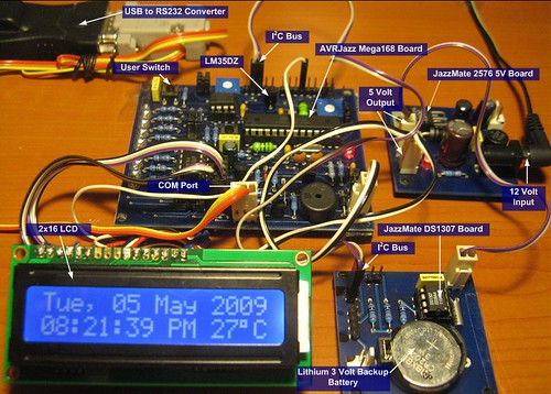
- Using 2×16 LCD (Hitachi HD44780U) to display the digital clock
- Displaying days of week, day of month, month and year
- Displaying hour (24 or 12 hour format), minute and second
- Displaying current room’s temperature in centigrade format
- Setup the clock using the UART (Universal Asynchronous Receive Transmit) to communicate with the Windows’s HyperTerminal application.

In order to achieve this goal we will use many of the AVR ATMega168 peripherals; this makes this digital clock project is a good learning tools to explore and use many of the ATMega168 microcontroller sophisticated peripherals at the same time. I would suggest you could read my previous blogs to understand the basic of how to use the LCD, ADC, PWM, I2C and UART Atmel AVR peripherals, before you continue with this tutorial:
- Using 2×16 LCD: AVR LCD Thermometer Using ADC and PWM Project
- UART Communication: Working with AVR microcontroller Communication Port Project
- I2C or TWI (Two Wire Interface): How to use I2C-bus on the Atmel AVR Microcontroller
The following is the list of hardware and software used in this project:
- AVRJazz Mega168 board from ermicro which base on the AVR ATmega168 microcontroller (board schema).
- JazzMate DS1307 Real Time Clock board from ermicro
- JazzMate 2576 5 volt switching power board from ermicro
- LCD hardware: one 2×16 LCD (Hitachi HD44780U), one 10K trimport, one TIP120 darlington transistor and one 4K7 resistor
- WinAVR for the GNU’s C compiler
- Atmel AVR Studio 4 for the coding and debugging environment.
- STK500 programmer from AVR Studio 4, using the AVRJazz Mega168 board STK500 v2.0 bootloader facility.


The AVR ATMega168 microcontroller is used as the I2C’s master whiles the DS1307 RTC is used as the I2C slave that provide accurate date and time function. The TIMER0 peripheral inside ATMega168 microcontroller is used to read the DS1307 RTC register every 1 second and display the value to the 2×15 LCD. The build in national semiconductor LM35DZ precision centigrade temperature sensor on the AVRJazz Mega168 board is served as the room’s temperature sensor that will give 1 mv/oC output to the microcontroller’s ADC (Analog to Digital) input port (PC1).
The 2×16 LCD display is operated in 4-bits data mode and connected to the ATMega168 PORTD (PD2, PD3, PD4, PD5, PD6 and PD7); the LCD backlight is controlled by the ATMega168 TIMER2 PWM (Pulse Width Modulation) port (PB3) through the Darlington transistor TIP120. The PWM is used to dimming the LCD backlight while our digital clock is in the setup mode; entering digital clock setup mode could be done by pressing the build in user button switch attached to the PORTB (PB0).

The last is the ATMega168 UART peripheral is used to setup our digital clock; using the AVRJazz Mega168 board build in RS323 voltage level converter; we could connect the RS232 communication (COM) port directly to the computer COM port or you could use the USB to RS232 converter as I did and use the MS Windows HyperTerminal program to enter our digital clock setup.

Ok that’s a brief explanation of the digital clock project circuit that we are going to walk through; now let’s take a look at the C code that makes this happen:
/*****************************************************************************
//  File Name    : avrclock.c
//  Version      : 1.0
//  Description  : DS1307 RTC AVR Microcontroller Clock
//  Author       : RWB
//  Target       : AVRJazz Mega168 Board
//  Compiler     : AVR-GCC 4.3.0; avr-libc 1.6.2 (WinAVR 20080610)
//  IDE          : Atmel AVR Studio 4.14
//  Programmer   : AVRJazz Mega168 STK500 v2.0 Bootloader
//               : AVR Visual Studio 4.14, STK500 programmer
//  Last Updated : 28 April 2009
*****************************************************************************/
#include <avr/io.h>
#include <util/delay.h>
#include <compat/twi.h>
#include <avr/interrupt.h>
#include <stdio.h>
#define BAUD_RATE 19200
#define MAX_TRIES 50
#define DS1307_ID    0xD0        // I2C DS1307 Device Identifier
#define DS1307_ADDR  0x00        // I2C DS1307 Device Address
#define I2C_START 0
#define I2C_DATA 1
#define I2C_DATA_ACK 2
#define I2C_STOP 3
#define ACK 1
#define NACK 0
#define LCD_HOME 0x02
#define LCD_NEXT_LINE 0xC0
#define LCD_CLEAR 0x01
#define LCD_1CYCLE 0
#define LCD_2CYCLE 1
// DS1307 Register Address
// Second: ds1307_addr[0]
// Minute: ds1307_addr[1]
// Hour  : ds1307_addr[2]
// Day   : ds1307_addr[3]
// Date  : ds1307_addr[4]
// Month : ds1307_addr[5]
// Year  : ds1307_addr[6]
#define HOUR_24 0
#define HOUR_12 1
char ds1307_addr[7];
char sdigit[3]={'0','0','\0'};
char *weekday[]={"Sun","Mon","Tue","Wed","Thr","Fri","Sat"};
char *month[]={"Jan","Feb","Mar","Apr","May","Jun","Jul","Aug","Sep","Oct","Nov","Dec"};
char hour_mode, ampm_mode;
void uart_init(void)
{
  UBRR0H = (((F_CPU/BAUD_RATE)/16)-1)>>8;	// set baud rate
  UBRR0L = (((F_CPU/BAUD_RATE)/16)-1);
  UCSR0B = (1<<RXEN0)|(1<<TXEN0); 		 // enable Rx & Tx
  UCSR0C=  (1<<UCSZ01)|(1<<UCSZ00);  	        // config USART; 8N1
}
int uart_putch(char ch,FILE *stream)
{
   if (ch == '\n')
    uart_putch('\r', stream);
   while (!(UCSR0A & (1<<UDRE0)));
   UDR0=ch;
   return 0;
}
int uart_getch(FILE *stream)
{
   unsigned char ch;
   while (!(UCSR0A & (1<<RXC0)));
   ch=UDR0;

   /* Echo the Output Back to terminal */
   uart_putch(ch,stream);

   return ch;
}
void ansi_cl(void)
{
  // ANSI clear screen: cl=\E[H\E[J
  putchar(27);
  putchar('[');
  putchar('H');
  putchar(27);
  putchar('[');
  putchar('J');
}
void ansi_me(void)
{
  // ANSI turn off all attribute: me=\E[0m
  putchar(27);
  putchar('[');
  putchar('0');
  putchar('m');
}
void ansi_cm(unsigned char row,unsigned char col)
{
  // ANSI cursor movement: cl=\E%row;%colH
  putchar(27);
  putchar('[');
  printf("%d",row);
  putchar(';');
  printf("%d",col);
  putchar('H');
}
void LCD_putch(unsigned char data)
{
  // LCD Upper 4 bits data (DB7,DB6,DB5,DB4)
  PORTD = (1<<PD3)|(1<<PD2)|(data & 0xF0);        // RS = 1, E = 1
  // E=0; write data
  PORTD &= ~(1<<PD3);
  _delay_us(1);

  // LCD Lower 4 bits data (DB3,DB2,DB1,DB0)
  PORTD = (1<<PD3)|(1<<PD2)|((data & 0x0F) << 4); // RS = 1, E = 1

  // E=0; write data
  PORTD &= ~(1<<PD3);
  _delay_ms(5);     // Wait for busy flag (BF)
}
void LCD_putcmd(unsigned char data,unsigned char cmdtype)
{
  // LCD Upper 4 bits data (DB7,DB6,DB5,DB4)
  PORTD = (1<<PD3)|(data & 0xF0);                 // RS = 0, E = 1
  // E=0; write data
  PORTD &= ~(1<<PD3);
  _delay_us(1);

  // cmdtype = 0; One cycle write, cmdtype = 1; Two cycle writes
  if (cmdtype) {
    // LCD Lower 4 bits data (DB3,DB2,DB1,DB0)
    PORTD = (1<<PD3)|((data & 0x0F) << 4);        // RS = 0, E = 1

    // E=0; write data
    PORTD &= ~(1<<PD3);
  }
  _delay_ms(5);    // Wait for busy flag (BF)
}
void initlcd()
{
  // Wait for more than 15 ms after VCC rises to 4.5 V
  _delay_ms(30);
  // Send Command 0x30
  LCD_putcmd(0x30,LCD_1CYCLE);
  // Wait for more than 4.1 ms
  _delay_ms(8);
  // Send Command 0x30
  LCD_putcmd(0x30,LCD_1CYCLE);
  // Wait for more than 100 us
  _delay_us(200);
  // Send Command 0x30
  LCD_putcmd(0x30,LCD_1CYCLE);
  // Function set: Set interface to be 4 bits long (only 1 cycle write).
  LCD_putcmd(0x20,LCD_1CYCLE);
  // Function set: DL=0;Interface is 4 bits, N=1; 2 Lines, F=0; 5x8 dots font)
  LCD_putcmd(0x28,LCD_2CYCLE);
  // Display Off: D=0; Display off, C=0; Cursor Off, B=0; Blinking Off
  LCD_putcmd(0x08,LCD_2CYCLE);
  // Display Clear
  LCD_putcmd(0x01,LCD_2CYCLE);
  // Entry Mode Set: I/D=1; Increment, S=0; No shift
  LCD_putcmd(0x06,LCD_2CYCLE);
}
void LCD_puts(char *s)
{
   while(*s != 0)      // While not Null
   {
     if (*s == '\n')
	   LCD_putcmd(LCD_NEXT_LINE,LCD_2CYCLE);  // Goto Second Line
     else
       LCD_putch(*s);
	 s++;
   }
}
/* START I2C Routine */
unsigned char i2c_transmit(unsigned char type) {
  switch(type) {
     case I2C_START:    // Send Start Condition
       TWCR = (1 << TWINT) | (1 << TWSTA) | (1 << TWEN);
       break;
     case I2C_DATA:     // Send Data with No-Acknowledge
       TWCR = (1 << TWINT) | (1 << TWEN);
	   break;
     case I2C_DATA_ACK: // Send Data with Acknowledge
       TWCR = (1 << TWEA) | (1 << TWINT) | (1 << TWEN);
	   break;
     case I2C_STOP:     // Send Stop Condition
	   TWCR = (1 << TWINT) | (1 << TWEN) | (1 << TWSTO);
	   return 0;
  }
  // Wait for TWINT flag set on Register TWCR
  while (!(TWCR & (1 << TWINT)));
  // Return TWI Status Register, mask the prescaller bits (TWPS1,TWPS0)
  return (TWSR & 0xF8);
}
char i2c_start(unsigned int dev_id, unsigned int dev_addr, unsigned char rw_type)
{
  unsigned char n = 0;
  unsigned char twi_status;
  char r_val = -1;
i2c_retry:
  if (n++ >= MAX_TRIES) return r_val;
  // Transmit Start Condition
  twi_status=i2c_transmit(I2C_START);

  // Check the TWI Status
  if (twi_status == TW_MT_ARB_LOST) goto i2c_retry;
  if ((twi_status != TW_START) && (twi_status != TW_REP_START)) goto i2c_quit;
  // Send slave address (SLA_W)
  TWDR = (dev_id & 0xF0) | (dev_addr & 0x07) | rw_type;
  // Transmit I2C Data
  twi_status=i2c_transmit(I2C_DATA);
  // Check the TWSR status
  if ((twi_status == TW_MT_SLA_NACK) || (twi_status == TW_MT_ARB_LOST)) goto i2c_retry;
  if (twi_status != TW_MT_SLA_ACK) goto i2c_quit;
r_val=0;
i2c_quit:
  return r_val;
}
void i2c_stop(void)
{
  unsigned char twi_status;
  // Transmit I2C Data
  twi_status=i2c_transmit(I2C_STOP);
}
char i2c_write(char data)
{
  unsigned char twi_status;
  char r_val = -1;
  // Send the Data to I2C Bus
  TWDR = data;
  // Transmit I2C Data
  twi_status=i2c_transmit(I2C_DATA);
  // Check the TWSR status
  if (twi_status != TW_MT_DATA_ACK) goto i2c_quit;
r_val=0;
i2c_quit:
  return r_val;
}
char i2c_read(char *data,char ack_type)
{
  unsigned char twi_status;
  char r_val = -1;

  if (ack_type) {
    // Read I2C Data and Send Acknowledge
    twi_status=i2c_transmit(I2C_DATA_ACK);
    if (twi_status != TW_MR_DATA_ACK) goto i2c_quit;
  } else {
    // Read I2C Data and Send No Acknowledge
    twi_status=i2c_transmit(I2C_DATA);
    if (twi_status != TW_MR_DATA_NACK) goto i2c_quit;
  }
  // Get the Data
  *data=TWDR;
  r_val=0;
i2c_quit:
  return r_val;
}
// Convert Decimal to Binary Coded Decimal (BCD)
char dec2bcd(char num)
{
  return ((num/10 * 16) + (num % 10));
}
// Convert Binary Coded Decimal (BCD) to Decimal
char bcd2dec(char num)
{
  return ((num/16 * 10) + (num % 16));
}
void Read_DS1307(void)
{
   char data;
   // First we initial the pointer register to address 0x00
   // Start the I2C Write Transmission
   i2c_start(DS1307_ID,DS1307_ADDR,TW_WRITE);
    // Start from Address 0x00
   i2c_write(0x00);
   // Stop I2C Transmission
   i2c_stop();

   // Start the I2C Read Transmission
   i2c_start(DS1307_ID,DS1307_ADDR,TW_READ);
   // Read the Second Register, Send Master Acknowledge
   i2c_read(&data,ACK);
   ds1307_addr[0]=bcd2dec(data & 0x7F);
   // Read the Minute Register, Send Master Acknowledge
   i2c_read(&data,ACK);
   ds1307_addr[1]=bcd2dec(data);
   // Read the Hour Register, Send Master Acknowledge
   i2c_read(&data,ACK);
   if ((data & 0x40) == 0x40) {
     hour_mode = HOUR_12;
	 ampm_mode=(data & 0x20) >> 5;   // ampm_mode: 0-AM, 1-PM
	 ds1307_addr[2]=bcd2dec(data & 0x1F);
   } else {
     hour_mode = HOUR_24;
	 ampm_mode=0;
     ds1307_addr[2]=bcd2dec(data & 0x3F);
   }
   // Read the Day of Week Register, Send Master Acknowledge
   i2c_read(&data,ACK);
   ds1307_addr[3]=bcd2dec(data);
   // Read the Day of Month Register, Send Master Acknowledge
   i2c_read(&data,ACK);
   ds1307_addr[4]=bcd2dec(data);
   // Read the Month Register, Send Master Acknowledge
   i2c_read(&data,ACK);
   ds1307_addr[5]=bcd2dec(data);
   // Read the Year Register, Send Master No Acknowledge
   i2c_read(&data,NACK);
   ds1307_addr[6]=bcd2dec(data);
   // Stop I2C Transmission
   i2c_stop();
}
void Write_DS1307(void)
{
   unsigned char i, hour_format;
   // Make sure we enable the Oscillator control bit CH=0 on Register 0x00
   ds1307_addr[0]=ds1307_addr[0] & 0x7F;
   // Start the I2C Write Transmission
   i2c_start(DS1307_ID,DS1307_ADDR,TW_WRITE);
   // Start from Address 0x00
   i2c_write(0x00);
   // Write the data to the DS1307 address start at 0x00
   // DS1307 automatically will increase the Address.
   for (i=0; i<7; i++) {
     if (i == 2) {
	   hour_format=dec2bcd(ds1307_addr[i]);
	   if (hour_mode) {
	     hour_format |= (1 << 6);
   	     if (ampm_mode)
	       hour_format |= (1 << 5);
         else
	       hour_format &= ~(1 << 5);
	   } else {
	     hour_format &= ~(1 << 6);
       }
	   i2c_write(hour_format);
	 } else {
       i2c_write(dec2bcd(ds1307_addr[i]));
     }
   }
   // Stop I2C Transmission
   i2c_stop();
}
// Implementing integer value from 00 to 99
char *num2str(char number)
{
   unsigned char digit;

   digit = '0';                       // Start with ASCII '0'
   while(number >= 10)                // Keep Looping for larger than 10
   {
     digit++;                         // Increase ASCII character
     number -= 10;                    // Subtract number with 10
   }

   sdigit[0]='0';                     // Default first Digit to '0'
   if (digit != '0')
     sdigit[0]=digit;                 // Put the Second digit
   sdigit[1]='0' + number;
   return sdigit;
}
char getnumber(unsigned char min, unsigned char max)
{
  int inumber;
  scanf("%d",&inumber);
  if (inumber < min || inumber > max) {
    printf("\n\nInvalid [%d to %d]!",min,max);
	_delay_ms(500);
	return -1;
  }
  return inumber;
}
ISR(TIMER0_OVF_vect)
{
  static unsigned char tenms=1;
  int iTemp;
  tenms++;                  // Read DS1307 every 100 x 10ms = 1 sec
  if (tenms >= 100) {
    cli();                                // Disable Interupt
    // Read DS1307
    Read_DS1307();

	// Display the Clock
	LCD_putcmd(LCD_HOME,LCD_2CYCLE);      // LCD Home
	LCD_puts(weekday[ds1307_addr[3] - 1]); LCD_puts(", ");
	LCD_puts(num2str(ds1307_addr[4])); LCD_puts(" ");
	LCD_puts(month[ds1307_addr[5] - 1]); LCD_puts(" ");
	LCD_puts("20"); LCD_puts(num2str(ds1307_addr[6]));
LCD_putcmd(LCD_NEXT_LINE,LCD_2CYCLE); // Goto Second Line
	if (hour_mode) {
	  LCD_puts(num2str(ds1307_addr[2])); LCD_puts(":");
	  LCD_puts(num2str(ds1307_addr[1])); LCD_puts(":");
	  LCD_puts(num2str(ds1307_addr[0]));

	  if (ampm_mode)
	    LCD_puts(" PM");
      else
	    LCD_puts(" AM");
	} else {
	  LCD_puts(num2str(ds1307_addr[2])); LCD_puts(":");
	  LCD_puts(num2str(ds1307_addr[1])); LCD_puts(":");
	  LCD_puts(num2str(ds1307_addr[0])); LCD_puts("   ");
    }
	// Set ADMUX Channel for LM35DZ Input
    ADMUX=0x01;
	// Start conversion by setting ADSC on ADCSRA Register
	ADCSRA |= (1<<ADSC);
	// wait until convertion complete ADSC=0 -> Complete
    while (ADCSRA & (1<<ADSC));
	// Get the ADC Result
	iTemp = ADCW;
    // ADC = (Vin x 1024) / Vref, Vref = 1 Volt, LM35DZ Out = 10mv/C
	iTemp = (int)(iTemp) / 10.24;

    // Dislay Temperature
	LCD_puts(" ");
	LCD_puts(num2str((char)iTemp));   // Display Temperature
	LCD_putch(0xDF);                  // Degree Character
	LCD_putch('C');                   // Centigrade
	tenms=1;
	sei();                            // Enable Interrupt
  }
  TCNT0=0x94;
}
// Assign I/O stream to UART
FILE uart_str = FDEV_SETUP_STREAM(uart_putch, uart_getch, _FDEV_SETUP_RW);
int main(void)
{
  char mode,ichoice;
  int icount;
  // Initial PORT Used
  DDRB = 0xFE;                 // Set PB0=Input, Others Output
  PORTB = 0;
  DDRC = 0;                    // Set PORTC as Input
  PORTC = 0;
  DDRD = 0xFF;                 // Set PORTD as Output
  PORTD = 0;

  // Define Output/Input Stream
  stdout = stdin = &uart_str;
  // Initial LCD using 4 bits data interface
  initlcd();
  LCD_putcmd(0x0C,LCD_2CYCLE);      // Display On, Cursor Off
  LCD_putcmd(LCD_CLEAR,LCD_2CYCLE); // Clear LCD
  // Initial ATMega168 UART Peripheral
  uart_init();
  // Initial ATMega168 TWI/I2C Peripheral
  TWSR = 0x00;   // Select Prescaler of 1
  // SCL frequency = 11059200 / (16 + 2 * 48 * 1) = 98.743 khz
  TWBR = 0x30;   // 48 Decimal
  // Initial ATMega168 ADC Peripheral
  ADCSRA = (1<<ADEN) | (1<<ADPS2) | (1<<ADPS1);
  // Free running ADC Mode
  ADCSRB = 0x00;
  // Disable digital input on ADC0 and ADC1
  DIDR0 = 0x03;
  // Initial ATMega168 PWM using Timer/Counter2 Peripheral
  TCCR2A=0b10000011;            // Fast PWM Mode, Clear on OCRA
  TCCR2B=0b00000100;            // Used fclk/64 prescaller
  OCR2A=0xFF;                   // Initial the OC2A (PB3) Out to 0xFF
  // Initial ATMega168 Timer/Counter0 Peripheral
  TCCR0A=0x00;                  // Normal Timer0 Operation
  TCCR0B=(1<<CS02)|(1<<CS00);   // Use maximum prescaller: Clk/1024
  TCNT0=0x94;                   // Start counter from 0x94, overflow at 10 mSec
  TIMSK0=(1<<TOIE0);            // Enable Counter Overflow Interrupt
  sei();                        // Enable Interrupt
  // Initial mode
  mode=0;
  for(;;)
  {
    // Check if Button is pressed than enter to the Setup Mode
    if (bit_is_clear(PINB, PB0)) {          // if button is pressed
	  _delay_us(100);                       // Wait for debouching
	  if (bit_is_clear(PINB, PB0)) {        // if button is pressed
		mode = 1;

	    cli();  // Disable Interrupt
	    LCD_putcmd(LCD_CLEAR,LCD_2CYCLE);   // Clear LCD
	    LCD_puts("Setup Mode");
        // Dimmming the LCD
	    for (icount=255;icount > 0;icount--) {
	      OCR2A=icount;
	      _delay_ms(3);
	    }
      }
    }
    if (mode) {
      ansi_me();
      ansi_cl();                            // Clear Screen
      ansi_cm(1,1);
      printf("AVRJazz Mega168 DS1307 RTC Setup");
	  ansi_cm(3,1);
	  printf("1. Time: %02d:%02d:%02d\n",ds1307_addr[2],ds1307_addr[1],ds1307_addr[0]);
	  printf("2. Mode 24/12: %d, AM/PM: %d\n",hour_mode,ampm_mode);
	  printf("3. Date: %02d-%02d-20%02d, Week Day: %d\n",ds1307_addr[4],ds1307_addr[5],ds1307_addr[6],ds1307_addr[3]);
	  printf("4. Save and Exit\n");
	  printf("5. Exit\n");
	  printf("\nEnter Choice: ");
	  if ((ichoice=getnumber(1,5)) < 0) continue;
	  switch (ichoice) {
	    case 1:  // DS1307 Time Setup
		  printf("\n\nHour [0-24]: ");
		  if ((ds1307_addr[2]=getnumber(0,24)) < 0) continue;
		  printf("\nMinute [0-59]: ");
		  if ((ds1307_addr[1]=getnumber(0,59)) < 0) continue;
		  printf("\nSecond [0-59]: ");
		  if ((ds1307_addr[0]=getnumber(0,59)) < 0) continue;
		  break;
        case 2:  // DS1307 Hour Mode Setup
		  printf("\n\nMode 0> 24, 1> 12: ");
		  if ((hour_mode=getnumber(0,1)) < 0) continue;
		  printf("\nAM/PM 0> AM, 1> PM: ");
		  if ((ampm_mode=getnumber(0,1)) < 0) continue;
		  break;
        case 3:  // DS1307 Date Setup
		  printf("\n\nWeekDay [1-7]: ");
		  if ((ds1307_addr[3]=getnumber(1,7)) < 0) continue;
	      printf("\nDate [1-31]: ");
		  if ((ds1307_addr[4]=getnumber(1,31)) < 0) continue;			  ;
		  printf("\nMonth [1-12]: ");
		  if ((ds1307_addr[5]=getnumber(1,12)) < 0) continue;
		  printf("\nYear [0-99]: ");
		  if ((ds1307_addr[6]=getnumber(0,99)) < 0) continue;
		  break;
        case 4:  // Save to DS1307 Register and Exit Setup
		  Write_DS1307();
		case 5:  // Exit Setup
		  mode = 0;
		  ansi_cl();
          // Illuminating the LCD
		  for (icount=0;icount < 255;icount++) {
	  	    OCR2A=icount;
	        _delay_ms(3);
	      }
		  TCNT0=0x94;
		  sei();   // Enable Interrupt
		  break;
	  }
    }
  }
  return 0;
}
/* EOF: avrclock.c */
The Real Time Clock (RTC) Chip
Clocked by 32.768 kHz crystal; the Maxim DS1307 is one of the popular I2C 8-pins RTC chip available on the market; other quite similar product is the Philips PCF8583 I2C 8-pins RTC chip which has additional programmable alarm, timer/counter and interrupt functions beside the standard time and date function. On this project we will focus on the Maxim DS1307 Real Time Clock chip but the principal we learn here could be applied to the Philips PCF8583 RTC chip as well.


Equipped with Automatic Power-Fail Detect and Switch Circuitry the Maxim DS1307 will continue to operate accurately even though the main power supply is lost and because it’s consumed less than 500nA on 3 volt lithium backup battery (48mAhr or greater), the DS1307 will continue to operate more 10 year in the absence of the main power supply (for more information please refers to the Maxim DS1307 datasheet).
The Maxim DS1307 RTC timekeeper registers start in address 0x00 to 0x06 and its stored the time and date value in Binary Code Decimal (BCD) format; it have one control register located in address 0x07 and 58 byte battery-backed nonvolatile (NV) RAM located in address 0x08 to 0x3F; this RAM could be used to store information such as the digital clock alarm setting or simple event reminder.
The DS1307 control register is used to enable or disable the square wave output on pin 7 (SQW/OUT); the frequency could be selected by setting the rate selection bits RS0 and RS1 and to enable the square wave output, simply set the SQWE bit to “1“. The SQW/OUT pin is an open collector output which required a pull up resistor in order to operate; you could use the square wave output to pulse your microcontroller project or other peripheral that needs it.

As I mention before the DS 1307 timekeeper registers store the value in BCD format; this type of format is different compared to the normal binary value, for example the number 38 could be represent in binary value as 0010 0110 or 0x26 in hex notation but in binary code decimal format the number 38 is represented as 0011 1000. The BCD format stores every decimal digit start from least significant digit (LSD) ( decimal 8 ) to most significant digit (MSD) (decimal 3) in four bits forms known as nibble, where each nibbles represent the decimal number 0 to 9.
The BCD format is use for simplicity reason, because it requires no complex calculation especially if the DS1307 data is directly pass through the BCD to Seven Segment Display driver such as well known 7446 (open collector) TTL IC series as this following picture:

Since in this project we use 2×16 LCD and HyperTerminal instead of the seven segments to display the time and date, therefore we have to convert the retrieved data from BCD to DECIMAL before we can use it; and convert the configuration data from DECIMAL to BCD before we store a new initial value to the DS1307 timekeeper registers.
The following C code functions are used for this purpose:
// Convert Decimal to Binary Coded Decimal (BCD)
char dec2bcd(char num)
{
  return ((num/10 * 16) + (num % 10));
}
// Convert Binary Coded Decimal (BCD) to Decimal
char bcd2dec(char num)
{
  return ((num/16 * 10) + (num % 16));
}
The clock halt bit (CH) in registers address 0x00 is used to stop the DS1307 internal oscillator when we set it to “1“; for example, we could use this feature to timed the time elapse event; but in this project we always set the CH bit to “0“. As said on the DS1307 datasheet, because the initial power-on state of this bit is not defined, it’s important to enable the internal oscillator bit (CH = 0) during the initial configuration.
The DS1307 RTC I2C Interface
The DS1307 RTC acts as an I2C slave device and communicate to the AVR ATMega168 I2C master controller though the I2C bus. As standard to all I2C devices; the DS1307 RTC has an unique 7 bits address consists of 4 bits device identification and 3 bits device physical address; the first 4 bits for this device identification is “1101” and the last 3 bits of physical address is always set to “000“, which mean we only can attached one DS1307 device on the same I2C bus.
The DS1307 RTC Slave Write Mode:
This operation mode is used when we want to store the data into the DS1307 registers such as setting the time and date or store data to the DS1307 nonvolatile RAM register.

After sending the I2C start condition and select the DS1307 device from I2C bus (sending ID and address), we set the DS1307 register pointer by sending the slave register address (e.g. 0x00 the first timekeeper register address). After the DS1307 send acknowledge than we could continue to send the data and the DS1307 will response with acknowledge and automatically increment the pointer register. We could continue send the data until all the data being written to the DS1307 timekeeper registers (address 0x00 to 0x06) finally we send the I2C stop condition. The same principal we could use to store data to the DS1307 RAM; instead of starting with the timekeeper register in address 0x00, for the nonvolatile RAM we could start in address 0x08, this will set the DS1307 pointer register to 0x08.
The Write_DS1307() C code function is used to implement this operation mode in this project. All the setup data is stored in ds1307_addr[] array variable (0 to 6); therefore by writing the content of this data to the corresponding DS1307 timekeeper register (address 0x00 to 0x06) we could set the DS1307 RTC:
// Write the data to the DS1307 address start at 0x00
// DS1307 automatically will increase the Address.
for (i=0; i<7; i++) {
  if (i == 2) {
    hour_format=dec2bcd(ds1307_addr[i]);
    if (hour_mode) {
      hour_format |= (1 << 6);
      if (ampm_mode)
        hour_format |= (1 << 5);
      else
        hour_format &= ~(1 << 5);
    } else {
	hour_format &= ~(1 << 6);
     }
     i2c_write(hour_format);
  } else {
    i2c_write(dec2bcd(ds1307_addr[i]));
  }
}
// Stop I2C Transmission
i2c_stop();
The DS1307 RTC Slave Write Pointer and Read Mode:
This operation mode is used when we want to read the data from the DS1307 registers such as time and date or read data from the DS1307 nonvolatile RAM register.

The data read operation is start by setting the DS1307 register pointer in address 0x00 using the write operation after sending the stop condition; then we continues to send I2C restart condition and again select the DS1307 ID with read instruction and follow by continuing reading all the DS1307 timekeeper registers (address 0x00 to 0x06). Each time the data is successfully read the master will send acknowledge (ACK) and the DS1307 will automatically increment the pointer register and continue to send the data stored in the pointed register until the master send the no-acknowledge (NACK); which tell the DS1307 to stop sending the data. Finally we send the stop condition to release the DS1307 device from the I2C bus.
The Read_DS1307() C code function is used to implement this operation mode in this project. All the data read from the DS1307 timekeeper register is stored in the ds1307_addr[] array variable; notice that for second and hour data we use special masking operation as follow:
// Read the Second Register, Send Master Acknowledge
i2c_read(&data,ACK);
ds1307_addr[0]=bcd2dec(data & 0x7F);
...
// Read the Hour Register, Send Master Acknowledge
i2c_read(&data,ACK);
if ((data & 0x40) == 0x40) {
  hour_mode = HOUR_12;
  ampm_mode=(data & 0x20) >> 5;   // ampm_mode: 0-AM, 1-PM
  ds1307_addr[2]=bcd2dec(data & 0x1F);
} else {
  hour_mode = HOUR_24;
  ampm_mode=0;
  ds1307_addr[2]=bcd2dec(data & 0x3F);
}
First we make sure to mask the CH (clock halt) bit on the DS1307 second register (address 0x00) data by using AND operator (data & 0x7F); and for the DS1307 hour register (address 0x02); we use 0x1F for 12 hour format or 0x3F for 24 hour format. On the last read (address 0x06) we use the i2c_read() function with NACK flag to tell the DS1307 to stop sending data:
// Read the Year Register, Send Master No Acknowledge
i2c_read(&data,NACK);
ds1307_addr[6]=bcd2dec(data);
// Stop I2C Transmission
i2c_stop();
Inside the C Code
The program start by initializing the ATmega168 ports used and we continue with the LCD device initiation, UART peripheral, TWI (two wire interfaces) peripherals (Atmel implementation of I2C protocol), ADC peripheral, PWM (Timer/Counter2) peripheral and the last is the TIMER0 peripheral. Most of the functions used in this project are based on my previous posted blogs mention above with some additional and minor modification especially for the I2C functions.
The UART Functions:
The UART functions are used to handle the communication with the PC:
- uart_init() function is used to initialize the ATMega168 UART peripheral
- uart_putch() function is used to put single character to the UART port
- uart_getch() function is used to read single character from the UART port
- ansi_cl() function is used to clear the ANSI emulation terminal screen
- ansi_me() function is used to turn off all attribute on the ANSI terminal emulation
- ansi_cm() function is used to move cursor on the ANSI terminal emulation
The application standard input and output stream is being redirected to both UART input and output with theses statements bellow:
// Assign I/O stream to UART
FILE uart_str = FDEV_SETUP_STREAM(uart_putch, uart_getch, _FDEV_SETUP_RW);
...
// Define Output/Input Stream
stdout = stdin = &uart_str;
The LCD Functions:
The LCD functions are used to control and display the data on the 2×16 LCD (Hitachi HD44780U) using 4-bit data mode:
- LCD_putch() function is used to display single character on the LCD
- LCD_putcmd() function is used to send LCD command (e.g. clear the LCD, move to second row, etc)
- initlcd() function is used to initialized the 2×16 LCD; this function will initialized the 2×16 LCD into 4-bit data mode
- LCD_puts() function is used to display a string on the LCD
- num2str() function is used to convert a numeric value to a string, we use this function to display numeric value on the LCD.
The DS1307 RTC I2C Functions:
The I2C functions are used to perform reading and writing to the I2C devices:
- i2c_transmit() function is used to transmit data to the I2C devices and wait for transmission done by monitoring the interrupt flag bit (TWINT) to be set.
- i2c_start() function is used to send the I2C start condition
- i2c_stop() function is used to send the I2C stop condition
- i2c_write() function is used to write data to the I2C slave device register
- i2c_read() function is used to read data from the I2C slave device register; the I2C master read operation could be selected to response with ACK (acknowledge) or NACK (no-acknowledge); this feature is used in the multiple data reading as in the DS1307 RTC.
- dec2bcd() function is used to convert decimal to the binary code decimal value
- bcd2dec() function is used to convert binary code decimal to the decimal value
- Read_DS1307() function is used to read the DS1307 RTC timekeeper registers
- Write_DS1307() function is used to write the DS1307 RTC timekeeper registers
Inside the infinite loop
We set the ATMega168 TIMER0 overflow interrupt on every 10ms, this could be achieve by setting the TIMER0 prescaler to 1024 and TIMER0 counter register (TCNT0) to 0x94 as this following code:
// Initial ATMega168 Timer/Counter0 Peripheral
TCCR0A=0x00;                  // Normal Timer0 Operation
TCCR0B=(1<<CS02)|(1<<CS00);   // Use maximum prescaller: Clk/1024
TCNT0=0x94;                   // Start counter from 0x94, overflow at 10 mSec
TIMSK0=(1<<TOIE0);            // Enable Counter Overflow Interrupt
sei();                        // Enable Interrupt
With the TCNT0 register set to 0x94 (148) and using AVRJazz Mega168 board clock frequency of 11059200 Hz; then we could calculate the TCNT0 over flow period as follow:
TIMER0 clock frequency with 1024 prescaler = 11.059.200 Hz / 1024 = 10.800 Hz
TCNT0 overflow period = (256 – 148) / 10.800 Hz = 0.01 Second = 10 ms
This mean the ISR(TIMER0_OVF_vect) or TIMER0 interrupt service register function will be called every 10ms; and every time its being called; the function will increase its static internal variable by one (tenms). When tenms variable reach 100 (means every 1 second); than we read the DS1307 timekeeper registers as well as the LM35DZ temperature sensor and display the data on the LCD.
Inside the for-loop (infinite loop) we simply read the on board user switch and if pressed then we enter the setup mode through the UART; the 8-bit Timer/Counter2 PWM is used to dim the LCD while in the setup mode by decreasing the ORC2A (output compare) register from 255 to 0 and to illuminate the LCD while in the digital clock mode (increasing the ORC2A register value to its maximum):
// Dimmming the LCD
for (icount=255;icount > 0;icount--) {
   OCR2A=icount;
   _delay_ms(3);
}
// Illuminating the LCD
for (icount=0;icount < 255;icount++) {
  OCR2A=icount;
  _delay_ms(3);
}
The getnumber() function is used to validate the user input; this function used the standard I/O C function scanf() to read the user input from the HyperTerminal application.
Compile and Download the Code to the board
Before compiling the code, we have to make sure the AVR Studio 4 configuration is set properly by selecting menu project -> Configuration Option, the Configuration windows will appear as follow:

Make sure the Device selected is atmega168 and the Frequency use is 11059200 hz.

After compiling and simulating our code we are ready to down load the code using the AVRJazz Mega168 bootloader facility. The bootloader program is activated by pressing the user switch and reset switch at the same time; after releasing both switches, the 8 blue LED indicator will show that the bootloader program is activate and ready to received command from Atmel AVR Studio 4 STK500 program.

We choose the HEX file and press the Program Button to down load the code into the AVRJazz Mega168 board. Now it’s time to relax and enjoy your hard work by watching your nice digital clock in action:
The Final Thought
One of the important used of the time and date integration in the embedded system is to provide the time and date stamp to the required information such as time attendance machine, automatic parking ticket, remote data logger, event elapse time and many more. By combining the I2C EEPROM and I2C RTC devices you could start build your own time and date stamped data logger; perhaps to answer a simple question such as when is the hottest temperature during this year; knowing this fact maybe make us more concern to the global warming issue that we are all facing today.
Bookmarks and Share


Related Posts
36 Responses to “Using Maxim DS1307 Real Time Clock with Atmel AVR Microcontroller”
Comment by rwb.
Currently this project is designed and tested only with the AVR ATMega168 microcontroller. For use with PIC16F877A you have to make major change to schema and the C program. My suggestion is to use newer microchip PIC microcontrller such as PIC16F887 (40 pins) or PIC16F886 (28 pins) instead of PIC16F877A
Comment by hectorvti.
Very good project. I’m still a beginner with programming so I need a little help from you. I think a little more difficult to use the serial port to setting the time, connected to the computer, use Hyper Terminal etc…
can you help me write the source code is as follows:
– set the time with buttons or joy…(no serial port)
– i dont know the DS1307 included the summertime/wintertime compensation
sorry for my english
by
Comment by rwb.
On the contrary; for the beginner programmer its easier to use the serial terminal instead of buttons, since using the buttons means you have to do special display menu in LCD and buttons to set both date and time. The DS1307 doesn’t support the summertime compensation.
Comment by hectorvti.
And do you give me some instruction, how to set the time with pushbuttons?
Comment by rwb.
A good example is the digital watch and the bed clock/alarm. Usually they have at least two buttons, the first button is used to choose the clock setup function e.g. hour, minute, and second. The second button is used to set the clock digit (increment). The same principle could be used for setting the date.
Comment by hectorvti.
hy
You set the TWBR register at 0x30 about 11 Mhz, but my mcu work with 16 Mhz in this case what is the value of TWBR?
Thank you for your help
Comment by rwb.
You could calculate your TWBR value using the I2C bus clock formula found on “How to use I2C-bus on the Atmel AVR Microcontroller” project
Comment by hectorvti.
Thank you,i calculated the value of TWBR and i think it the good value for the 16 Mhz is 0x43. Is there anything else you need to change because of the 16 Mhz?
Comment by hectorvti.
I booted your C code to my Atmel 328P…that is OK,but 6 secounds period stop for about 2 secounds and then start again,and the temperature value is only 99’C!
Do you know, what is the problem?
Comment by rwb.
There are many factor when the program didn’t work, therefore you need to break it one by one. First make sure all the hardware work properly e.g. I/O port, temperature sensor, RS232, and RTC chip. Next debug your program on each microcontroller peripherals e.g. I/O, UART, ADC, and I2C.
Comment by arss.
Hi,
Very nice toturial, but i have a question. The slave address of the DS1307 is not 0x68?
Comment by rwb.
Yes is not 0x68, because the DS1307 slave address byte contains the 7-bit (i.e. 1101000) followed by the direction bit read (1) or write (0), therefore the complete DS1307 slave address for reading is 11010001 (0xD1) or writing is 11010000 (0xD0).
Comment by firstoption.
Dear sir,thank you very much for this wonderful tutorial.it has really assisted me in my final year project i am doing now.i am using atmel xmega256a3 and DS32B35 RTC.So your tutorial actually addresed some of my problems.thank you for taking part of your time to produce this tutorial.
Sir i need your guide on how to copy the content of an array to a pointer.In order to display the content of RTC to the touchscreen LCD im using,I need to send this command(12,1,53)%256 to Lcd.below are my codes but it was not giving me the desired result when i ran it.i have very little experience in C programming and i will be very glad if you could put me through.
char SendCommand[3]={12,1,53};// i arranged the command in //array format
char *TempData;
char *ActualData;
int i;
TempData=SendCommand;
for(i=0;i<3;i++)
{ ActualData=TempData;
*TempData++
}
what i intend to achieve with the above code is to copy the content of my array SendCommand[] into the pointer *ActualData. Sir i would be very glad if you could be of help.Once again thank you for this tutorial.
Best regards.
Comment by rwb.
Basic C language pointer:
A pointer is a variable that contain the address (location) of the data. Therefore this following code will assigned the address value:
char SendCommand[3]={12,1,53};
char *TempData;
char *ActualData;
TempData = SendCommand; // Assigned SendCommand Address to TempData
…
ActualData=TempData; // Assigned TempData Address to ActualData
…
To get the pointer variable actual data on C language we use the “*” sign.
printf(“The data: %d\n”,*ActualData);
By incrementing the pointer address, you could get the next array data.
ActualData++;
printf(“The Next data: %d\n”,*ActualData);
I suggest to read a good C language book such as “The C Programming Language” by Brian W.Kernighan and Dennis M.Ritchie for more information.
Comment by firstoption.
dear sir,
thank you for your quick and detailed explanation.i really appreciate your kind gesutre.i will do just as you adviced.best regards.
Comment by bertstino.
sir:
Re avrclock. I tried AVR studio 4 and the hex file simulated in Proteus ISIS, but the results in the virtual terminal is garbage. Also the screen of the LCD always displays- SET-UP MODE. Is there any difference using the Atmega 168 development board and using the Proteus ISIS ( with same schematic as the Atmega 168 development board)? I also tried your tutorial in RS232, same thing happened, Vitual terminal in Proteus ISIS simulator is garbage. I followed the correct baud rate and CPU clock speed. Virtual terminal is a direct TTL level that can be connected directly to Tx/Rx pin of the microcontroller.
Where could be wrong? Would appreciate your kind assistance.
Thank you.
Comment by rwb.
I’ve never simulate all the project in this blog on Proteus ISIS software because I prefer to program directly the Microcontroller hardware rather than simulate it on the Proteus ISIS software, therefore I suggest to ask directly this issue on their forum.
Anyway the AVRJazz Mega168 development board use 11059200 Hz crystal resonator. Basically if the virtual terminal give you garbage, mean the clock and the baud rate is not set correctly.
Comment by bertstino.
I got it! I added #define F_CPU (clock freq)in the code and its no longer garbage. Will figure out though why for the example:
1. AVRclock. No clock display in the LCD. Also, no display of temperature.
2. RS232. Screen keeps on scrolling-up when I enter a guess number.
Where could be the problem?
Comment by rwb.
This is one example of the different between using the real circuit and the simulation. In the real circuit you don’t need to include the F_CPU in the C code as the compiler will automatically insert it for you using “-DF_CPU=11059200UL” argument base on the frequency option setup on the AVR Studio IDE.
I think you should post this issue on the Proteus ISIS user forum.
Comment by bertstino.
I finally got it working in the simulator really by adding F_CPU (clock freq). I like to simulate before buying the actual hardware or development board, because in the simulator, you are not limited with hardware materials and cost. Then when you figure out that you got what you want, then its time to buy the hardwares and build the circuit. Thanks for your tutorial, you’re great and your code is really fantastic and very encouraging to learn embedded C in more depth. It helps a lot of experimenters like me.
Comment by Mahdieh.
Dear Sir,
Thank you for your best and complete tutorial.
I really appreciate taking your time to produce it.
every line has description and this is wonderful.
I have a request!
Would you please upload twi.h library for download?
Thank you in anticipation.
Comment by Mahdieh.
I found it,but thank you very much.
Comment by firstoption.
Good day sir,
please i need your support and guide on how to solve the problem of this DS32B35 RTC.i have programmed the RTC and it is working but the operation is not stable.it worked for only 3hours then stopped.i re-set it 3-4 times but the same thing happened,worked for about 3hours then stopped.
i do not know if the problem is from the real time clock or from my code.i have tried to look for the likely cause of this hanging but unfortunately i could not figure it out.
Sir,i will highly appreciate your further guide and support in this regard.below is the while loop i used to read the RTC and then display it on my Lcd.
while(1)
{
_delay_ms(550);
DisplayCurrentTime();
_delay_ms(550);
}
the above loop is not in my main program,it is in another function which is called by the main program.i do not know if this could have any effect on the operation of the clock.once again thank you for the usual support.
best regards.
Comment by rwb.
Just curious, why you used 550ms twice (total more than 1 seconds) in your loop?
Comment by Jirka.
Hello.
This is a great project. But I have a small problem. I do not know how to get my DS1307 generate 1Hz signal. thanks a lot
Comment by rwb.
Read the “The Real Time Clock (RTC) Chip” section in this project, you need to set the SQWE bit at DS1307 address 07H.
Comment by Jirka.
Yes. But how do I set those at 07h RS1 and RS2. Still I can not send him good data.
Comment by Jirka.
I tried this sequence, but still on my DS1307 output signal appeared. Do you know where I could make a mistake?
ds1307_addr[7] = 0x10;
Write_DS1307();
Comment by Jirka.
Yes. I used 10k puillup resistors.
Comment by Jirka.
Sorry. But I make a very big mistake.
[code]
void Write_DS1307(void)
{
…
for (i=0; i<7; i++) {
…
} else {
i2c_write(dec2bcd(ds1307_addr[i]));
}
}
// Stop I2C Transmission
i2c_stop();
}
[/code]
variable 'i' I raise in value 7 But it has to be set to 8 😉
After this correction it work:
[code]
ds1307_addr[7] = 0×10;
Write_DS1307();
[/code]
Comment by altF4.
Hi, I like to try this progam within avrstudio,
but at building time I got this error:
[code]cc1.exe: error: unrecognized command line option
“-mmcu=atmega168”
[/code]
I’ve setup the avrstudio with the following configuration
avr-gcc > C: C:<WinAVR-20100110\utils\bin\make.exe
Best regards
Comment by altF4.
Sorry,
after typing that previous issue
I’ve discovered the error
The avr-gcc must not been the “avr32-gcc.exe”
but the “avr-gcc.exe” distribution.
Sorry for that tedious question.
Best regards
Comment by mayurkhan.
Hi sir i am implementing RTC using DS1307. I just want to know that which function from RTC_read or RTC_Set should be called first. If i using SER_RTC And Read_RTC then which function should i call first. I am attaching my 2 functions.
void SetRTC
(
unsigned char lucHour,
unsigned char lucMinutes,
unsigned char lucSeconds,
unsigned char lucDate,
unsigned char lucMonths,
unsigned char lucYears)
{
ewrite ( RTCADD, SECONDS, conver2bcd(lucSeconds) ); WCLR;
ewrite ( RTCADD, MINUTES, conver2bcd(lucMinutes) ); WCLR;
ewrite ( RTCADD, CENT_HOURS, conver2bcd(lucHour) ); WCLR;
ewrite ( RTCADD, DATE, conver2bcd(lucDate) ); WCLR;
ewrite ( RTCADD, MONTH, conver2bcd(lucMonths) ); WCLR;
ewrite ( RTCADD, YEARS, conver2bcd(lucYears) ); WCLR;
}
void ReadRTC(void)
{
unsigned char value=0;
value = e24c64read(EROMADD,0);
value = eread( RTCADD, CENT_HOURS );
gucHours = conver2hex (value);
value = eread( RTCADD , MINUTES );
gucMinutes = conver2hex (value);
value = eread( RTCADD , SECONDS );
gucSeconds = conver2hex (value);
value = eread( RTCADD, DATE );
gucDate = conver2hex (value);
value = eread( RTCADD , MONTH );
gucMonth = conver2hex (value);
value = eread( RTCADD , YEARS );
gucYear = conver2hex (value);
//tRTC(gucHour,gucMinutes,gucSeconds,gucDate,gucMonth
}

Comment by diya.
this is fantastic..I like to develop this project but I need to used the pic 16F877A and code prgramme C language that compile using PIC C compiler..how I should troubleshoot the schematic and programme?