Blog Entry
AVR LCD Thermometer Using ADC and PWM Project
January 3, 2009 by rwb, under Microcontroller.
Sometimes we need our microcontroller to interact with more human readable information. It will be better for us if we could make it display the words not just blinking the LED. Today most modern gadget such as mobile phone and PDA, use LCD (Liquid Crystal Display) for interacting with us. In this project we will learn how to use the 2×16 LCD for displaying the room’s temperature.
Actually driving the LCD hardware directly is a complex task, but luckily we don’t have to do that; in the market they have already put it together in one package the LCD display hardware and the microcontroller that control it, so our task will be easier now as we only talk to the build in microcontroller inside. The most famous on the market is the 2×16 LCD with LED backlight using Hitachi HD44780U or the equivalent microcontroller, this 80 pins microcontroller is a special dot matrix LCD driver controller with low power consumption and able to use 4-bit data or 8-bit data interface; my suggestion is to have this HD44780U datasheet near you as we walk through this project.

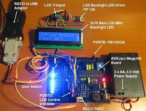
In this project we will use the AVRJazz Mega168 board from ermicro with has build in precision centigrade temperature sensor LM35DZ connected to the PORTC (ADC1), the diagram bellow will show you how to connect the 2×16 LCD to the board:

The simple 2×16 LCD with 16 pins connection is shown on the first schema, usually the VO pin for controlling the LCD contrast is connected to the trimpot that works as voltage divider, but because the board and LCD is using the same supply 4.5 volt and the voltage needed is very small (less then 0.25 volt) for readable/normal contrast you could connect it directly to the ground.
The enhance version of this 2×16 LCD connection schema is shown on the right; on this schema we use the PWM signal to power the LCD backlight LED through the TIP 120 Darlington pair transistor but you could change this with other type of transistor that capable of handling more than 100mA needed by the LCD backlight LED such as BC639 or it’s equivalent.
We will use the PWM to switch the LCD backlight LED on and off; because it use a lot of power (about 100mA), so instead of turn the LED just on and off, we just make it gradually bright when we turn on and gradually dark when we turn off. Ok let’s take a look at the C code that makes this work:
//***************************************************************************
//  File Name    : templcd.c
//  Version      : 1.0
//  Description  : Temperature Sensor Using LCD
//  Author(s)    : RWB
//  Target(s)    : AVRJazz Mega168 Learning Board
//  Compiler     : AVR-GCC 4.3.0; avr-libc 1.6.2 (WinAVR 20080610)
//  IDE          : Atmel AVR Studio 4.14
//  Programmer   : AVRJazz Mega168 STK500 v2.0 Bootloader
//               : AVR Visual Studio 4.14, STK500 programmer
//  Last Updated : 27 Dec 2008
//***************************************************************************
#include <avr/io.h>
#include <util/delay.h>
#define LCD_HOME 0x02
#define LCD_NEXT_LINE 0xC0
#define LCD_CLEAR 0x01
#define LCD_1CYCLE 0
#define LCD_2CYCLE 1
void LCD_putch(unsigned char data)
{
  // LCD Upper 4 bits data (DB7,DB6,DB5,DB4)
  PORTD = (1<<PD3)|(1<<PD2)|(data & 0xF0);        // RS = 1, E = 1
  // E=0; write data
  PORTD &= ~(1<<PD3);
  _delay_us(1);

  // LCD Lower 4 bits data (DB3,DB2,DB1,DB0)
  PORTD = (1<<PD3)|(1<<PD2)|((data & 0x0F) << 4); // RS = 1, E = 1

  // E=0; write data
  PORTD &= ~(1<<PD3);
  _delay_ms(5);     // Wait for busy flag (BF)
}
void LCD_putcmd(unsigned char data,unsigned char cmdtype)
{
  // LCD Upper 4 bits data (DB7,DB6,DB5,DB4)
  PORTD = (1<<PD3)|(data & 0xF0);                 // RS = 0, E = 1
  // E=0; write data
  PORTD &= ~(1<<PD3);
  _delay_us(1);

  // cmdtype = 0; One cycle write, cmdtype = 1; Two cycle writes
  if (cmdtype) {
    // LCD Lower 4 bits data (DB3,DB2,DB1,DB0)
    PORTD = (1<<PD3)|((data & 0x0F) << 4);        // RS = 0, E = 1

    // E=0; write data
    PORTD &= ~(1<<PD3);
  }
  _delay_ms(5);    // Wait for busy flag (BF)
}
void LCD_init()
{
  // Wait for more than 15 ms after VCC rises to 4.5 V
  _delay_ms(30);
  // Send Command 0x30
  LCD_putcmd(0x30,LCD_1CYCLE);
  // Wait for more than 4.1 ms
  _delay_ms(8);
  // Send Command 0x30
  LCD_putcmd(0x30,LCD_1CYCLE);
  // Wait for more than 100 us
  _delay_us(200);
  // Send Command 0x30
  LCD_putcmd(0x30,LCD_1CYCLE);
  // Function set: Set interface to be 4 bits long (only 1 cycle write).
  LCD_putcmd(0x20,LCD_1CYCLE);
  // Function set: DL=0;Interface is 4 bits, N=1; 2 Lines, F=0; 5x8 dots font)
  LCD_putcmd(0x28,LCD_2CYCLE);
  // Display Off: D=0; Display off, C=0; Cursor Off, B=0; Blinking Off
  LCD_putcmd(0x08,LCD_2CYCLE);
  // Display Clear
  LCD_putcmd(0x01,LCD_2CYCLE);
  // Entry Mode Set: I/D=1; Increament, S=0; No shift
  LCD_putcmd(0x06,LCD_2CYCLE);
}
void LCD_puts(char *s)
{
   while(*s != 0)      // While not Null
   {
     if (*s == '\n')
       LCD_putcmd(LCD_NEXT_LINE,LCD_2CYCLE);  // Go to Second Line
     else
       LCD_putch(*s);
     s++;
   }
}
// LCD_putnum: Implementing integer value from -999 to 999
void LCD_putnum(int number)
{
   unsigned char digit;
   if (number < 0) {
     LCD_putch('-');
	 number = -1 * number;
   }
   digit = '0';                       // Start with ASCII '0'
   while(number >= 100)               // Keep Looping for larger than 100
   {
     digit++;                         // Increase ASCII character
     number -= 100;                   // Subtract number with 100
   }
   if (digit != '0')
     LCD_putch(digit);                // Put the Third digit
   digit = '0';                       // Start with ASCII '0'
   while(number >= 10)                // Keep Looping for larger than 10
   {
     digit++;                         // Increase ASCII character
     number -= 10;                    // Subtract number with 10
   }

   if (digit != '0')
     LCD_putch(digit);                // Put the Second digit
   LCD_putch('0' + number);           // Put the First digit
}
int main(void)
{
	unsigned int iTemp,iCount;
	unsigned char LCDStatus;

	// Initial PORT Used
	DDRB = 0xFE;                  // Set PB0=Input, Others Output
	PORTB = 0;
	DDRC = 0;                     // Set PORTC as Input
	PORTC = 0;
	DDRD = 0xFF;                  // Set PORTD as Output
	PORTD = 0;
	// Initial LCD using 4 bits data interface
	LCD_init();
	// Set LCD Display: D=1; Display On, C=0; Cursor Off, B=0; Blinking Off
	LCD_putcmd(0x0C,LCD_2CYCLE);  // Display On, Cursor Off
	LCD_puts("AVRJazz Mega168\n");

	// Initial PWM (using Timer/Counter2)
        TCCR2A=0b10000011;            // Fast PWM Mode, Clear on OCRA
        TCCR2B=0b00000100;            // Used fclk/64 prescaller
	OCR2A=0;                      // Initial the OC2A (PB3) Out to 0
	LCDStatus=0;                  // Initial LCD On Status Flag
        // Set ADMUX Channel for LM35DZ Input
	ADMUX=0x01;
        // Initial the ADC Circuit
	ADCSRA = (1<<ADEN) | (1<<ADPS2) | (1<<ADPS1);
	// Free running Mode
	ADCSRB = 0x00;
	// Disable digital input on ADC1
	DIDR0 = 0x02;

	for(;;) {                     // Loop Forever
	  if (bit_is_clear(PINB, PB0)) {          // if button is pressed
	    _delay_us(100);                       // Wait for debouching
	    if (bit_is_clear(PINB, PB0)) {        // if button is pressed
	      LCDStatus=~LCDStatus;               // Toggle LCDStatus

	      if (LCDStatus) {
	        for (iCount=0;iCount < 255;iCount++) {
		  OCR2A=iCount;	                  // Increase OCR2A
		  _delay_ms(3);
		}
	      } else {
	        for (iCount=255;iCount > 0;iCount--) {
		  OCR2A=iCount;		          // Decrease OCR2A
		  _delay_ms(3);
	        }
	      }
            }
          }
	  // Start conversion by setting ADSC on ADCSRA Register
	  ADCSRA |= (1<<ADSC);
	  // wait until convertion complete ADSC=0 -> Complete
          while (ADCSRA & (1<<ADSC));
	  // Get First ADC Result
	  iTemp = ADCW;
	  // Start conversion by setting ADSC on ADCSRA Register
	  ADCSRA |= (1<<ADSC);
	  // wait until convertion complete ADSC=0 -> Complete
          while (ADCSRA & (1<<ADSC));
          // Get Second ADC Result
	  iTemp += ADCW;
	  // Start conversion by setting ADSC on ADCSRA Register
	  ADCSRA |= (1<<ADSC);
	  // wait until convertion complete ADSC=0 -> Complete
          while (ADCSRA & (1<<ADSC));
	  // Get the Final ADC Result
	  iTemp += ADCW;
          // ADC = (Vin x 1024) / Vref, Vref = 1 Volt, LM35DZ Out = 10mv/C
	  // Calculate the average value for 3 ADC samples result
	  iTemp = (int)(iTemp/3) / 10.24;
	  // Print ADC Value
          LCD_putcmd(LCD_HOME,LCD_2CYCLE);      // LCD Home
	  LCD_putcmd(LCD_NEXT_LINE,LCD_2CYCLE); // Go to Second Line

 	  LCD_puts("Temp: ");
	  LCD_putnum(iTemp);         // Display Temperature
	  LCD_putch(0xDF);           // Degree Character
	  LCD_putch('C');            // Centigrade
	  _delay_ms(50);
       }
       return 0;	                            // Standard Return Code
}
// EOF: templcd.c
Inside the C Code
The program is start by initialized the ATmega168 port used and continue with initialized the LCD, AVR ATmega168 PWM peripheral, ADC peripheral and finally go into the endless loop where we read the button status connected to the PB0 on PORTB, do the ADC conversion and display the value to the LCD. Bellow is the description of all functions used in this code:
- LCD_putch(); this function is use to send a single character to the LCD controller
- LCD_putcmd(); this function is use to send a command or instruction to the LCD controller
- LCD_puts(); implementation of C puts() function for the LCD, which display a terminated null string to the LCD
- LCD_putnum(); this function is use to display integer value to the LCD only implement the value from -999 to 999 which is more adequate for our project
- LCD_init(); this function is use to initialized the LCD controller.
Interfacing with the HD44780U LCD Controller
To talk with other microcontroller we need to understand the protocol used by our guest microcontroller, the time diagram below provide us with that information:

Looking at the timing diagram above, we could understand the reason why R/W signal is grounded (logical “0“) in this project schema. In order to reduce the number of port lines required to interface with the LCD controller; we just simply using _delay_ms() instruction to wait instead of reading the busy flag (BF) which required the R/W line to be logical “1“. Therefore by always use the write operation (R/W=0) we could reduce the number of PORT lines to 6 instead of 7:

The reason of starting with PD2 instead of PD0 is to reserve the PD0 and PD1 for other usage, because the PD0 and PD1 port on AVR ATmega168 is the UART (Universal Asynchronous Receive Transmit) port that can be used to connect with other UART peripherals such as barcode reader or magnetic card reader.
The principal of writing the instruction and data to the LCD controller according to the timing diagram above are:
A. Write to the instruction register:
This LCD writing instruction is implemented in the LCD_putcmd() function:
- Put the high 4 bit order; select the instruction register (RS=0) and enable data writing (E=1) to the PORTD
- Make E fall down to zero so the LCD controller will read the data and wait for data stabilization; implemented in _delay_us(1) call function.
- Put the low 4 bit order; select the instruction register (RS=0) and enable data writing (E=1) to the PORTD
- Make E fall down to zero so the LCD controller will read the data and wait for instruction complete operation; implemented in _delay_ms(5) call function.
B. Write to the data register:
This LCD write data is implemented in the LCD_putch() function:
- Put the high 4 bit order; select the data register (RS=1) and enable data writing (E=1) to the PORTD
- Make E fall down to zero so the LCD controller will read the data and wait for data stabilization; implemented in _delay_us(1) call function.
- Put the low 4 bit order; select the data register (RS=1) and enable data writing (E=1) to the PORTD
- Make E fall down to zero so the LCD controller will read the data and wait for instruction complete operation; implemented in _delay_ms(5) call function.
The LCD Controller Initiation
Before we can use the LCD we have to initiate the controller by using the recommended steps (refer to the HD44780U datasheet for complete description):

This LCD initiation is implemented in the LCD_init() function, because during initiation we need to have 1 cycle of E (enable) data signal pulse, therefore the LCD_putcdm() used the second parameter (cmdtype) to differentiate it. After we finish the 4 bit data initiation, all the commands to the instruction register always use the 2 cycle of E (enable) data signal pulse.
The PWM Peripheral Initiation
The ATmega168 is loaded with 6 PWM channels and for this project we will use the 8 bit Timer/Counter2 to generate PWM signal to power the LCD backlight LED through the TIP 120 Darlington pair transistor. The 8 bit Timer/Counter2 PWM have two interdependent PWM output the first one is OC2A (PB3, PIN 17) and the second one is OC2B (PD3, PIN 5); we will use the OC2A pin as the PWM output.
The PWM initiation involve two registers in AVR ATmega168; the first one is TCCR2A (timer/counter control register A) to activate the waveform generator output OC2A to the port PB3 (COM2A1 and COM2A0 bits) and for selecting the PWM type (WGM21 and WGM20 bits); the second one is TCCR2B (timer/counter control register B) to select the prescaler frequency for the timer/counter (CS22, CS21and CS20 bits) and for selecting the PWM type (WGM22 bit).


From the table above we will set the TCCR2A register with COM2A1=1 and COM2A0=0 for Clear OC2A on Compare Match; WGM1=1 and WGM0=0 for fast PWM mode.


By choosing the 64 prescaler factor the setting on register TCCR2B will be CS22=1, CS21=0 and CS20=0 also for fast PWM mode the WGM22 bit is set to logical “0“. The complete C code for setting the PWM registers:
TCCR2A=0b10000011;            // Fast PWM Mode, Clear on OCRA
TCCR2B=0b00000100;            // Used fclk/64 prescaller
OCR2A=0;                      // Initial the OC2A (PB3) Out to 0
The OCR2A register is used by the waveform generator inside the ATmega168 PWM peripheral as the comparison value to the TCNT2 timer/counter register, so every time the TCNT2 register value equal to OCR2A register value (or reach maximum 255) then the OC2A output will be logical “0” otherwise the OC2A output will be logical “1“. By initialized this OCR2A register to “0” means the OC2A output will always on the logical “0” state, which turn off the TIP 120 Darlington pair transistor and the LCD backlight LED.
Changing the OCR2A value from 0 to 255 (maximum) will vary the PWM duty cycle from 0% to 100% and vice versa; this technique is used to make the LCD backlight LED slowly turn on from dark to bright when we press the AVRJazz Mega168 user switch (connecting to the PB0 of PORTB) and again slowly turn off from bright to dark when we press the button again.
The ADC Peripheral Initiation
This heavy loaded peripheral 8-bit 28 pins microcontroller is also equipped with 6 10-bit ADC channels (PDIP package; 8 channels on TQFP package) and has a build in temperature sensor too. This temperature sensor can be access by selecting the ADC8 channel and reading the value from this channel using the 1.1 volt internal voltage references. But on this project we will not use this build in temperature sensor instead we will use the AVRJazz Mega168 board temperature sensor which used the LM35DZ precession centigrade temperature sensor from national semiconductor.
This TO-92 package sensor has the output of 10mV/oC, means every 1 degree Celsius of increment in the temperature measured will produce 10 mV of output:

This linear voltage output behavior makes our job easier to get the temperature value produced by the ADC conversion using this formula:

Where Vin is the LM35DZ output voltage and the Vref is the reference voltage used by the ATmega168 ADC circuit, by using 1 Volt external reference voltage the ADC output for 100 degree Celsius can be calculated as follow:
ADC = (Vin x 1024) / Vref = (100 x 10mV x 1024) / 1 = 1024
By dividing the result with 10.24, we will get 100; this is the exact temperature value measured by the sensor. The 1 volt external reference voltage can be set by adjusting the voltage adjust trimpot on the AVRJazz Mega168 board and measure the voltage on the voltage reference measurement terminal using the multimeter:

The ADC peripheral in the ATmega168 microcontroller can be activated by these following steps:
1. Selecting the ADC reference voltage, ADC result representation and ADC channel in the ADMUX register


Because we are using the external reference voltage then we set the REFS1=0 and REFS0=0. The 10-bit ADC result will be placed in the ADCH and ADCL registers; the way this ADC peripheral put the result in these registers is depend on the ADLAR bit in ADMUX register when we set to logical “0” the highest 2 bits will be put in ADCH and the 8 lowest bits will be put in ADCL; when we set to logical “1” the highest 8 bits will be put in ADCH while the lowest 2 bit will be put in ADCL.
In WinAVR C language, we can retrieve this 10 bit value form the special defined macro substitution ADCW which contain both ADCH and ADCL value; therefore we just set this ADALR bit to logical “0“.
// Set ADMUX Channel for LM35DZ Input
ADMUX=0x01;
2. Enable the ADC peripheral and select the prescale frequency in the ADCSRA register


The successive approximation ADC method used in ATmega168 ADC peripheral required the input clock from 50 kHz to 200 kHz for maximum resolution; by choosing the 64 division factor we will get the frequency about 172.8 kHz (the AVRJazz Mega168 board crystal 11.0592 MHz divided by 64) . To power on the ADC circuit inside the ATmega168 microcontroller simply make the ADEN bit to logical “1“.
// Initial the ADC Circuit
ADCSRA = (1<<ADEN) | (1<<ADPS2) | (1<<ADPS1);
We just leave the ADATE, ADIF and ADIE bits to logical “0“, these bits is used when want to use the auto trigger ADC conversion (ADATE) or rising interrupt when ADC conversion complete (ADIF and ADIE).
3. Choose the auto trigger selection in ADCSRB register


In this project we use free running mode, this mean every time we instruct to ADC peripheral to do the conversion by setting the ADSC bit in ADCSRA register to logical “1” it will start the conversion right away and when it finish the ADC peripheral will set the ADSC bit to logical “0“.
// Free running Mode
ADCSRB = 0x00;
We just leave the analog comparator multiplexer enable bit (ACME) to logical “0“.
4. The last step is to disable the digital input in the DIDR0 register

By disabling the digital input on the analog input channel, according to Atmel we could reduce the power consumption of the microcontroller, again we just follow the instruction by setting the ADC1D bit to logical “1“; we disable the digital input on this channel.
// Disable digital input on ADC1
DIDR0 = 0x02;
The endless loop Code
Inside this endless loop code we do 3 things; first we read the user switch status which work as a toggle switch to turn on and off the LCD backlight LED using PWM, secondly we start the ADC conversion and wait to complete by keep looping until the ADSC bit in ADCSRA register is set to logical “0” by the ADC peripheral.
// Start conversion by setting ADSC on ADCSRA Register
ADCSRA |= (1<<ADSC);
// wait until convertion complete ADSC=0 -> Complete
while (ADCSRA & (1<<ADSC));
// Get First ADC Result
iTemp = ADCW;
The result is put in iTemp variable, for more accurate result we read the LM35DZ value three times and use the average result:
// ADC = (Vin x 1024) / Vref, Vref = 1 Volt, LM35DZ Out = 10mv/C
// Calculate the average value for 3 ADC samples result
iTemp = (int)(iTemp/3) / 10.24;
Finally we put the result to the LCD display.
// Print ADC Value
LCD_putcmd(LCD_HOME,LCD_2CYCLE);      // LCD Home
LCD_putcmd(LCD_NEXT_LINE,LCD_2CYCLE); // Go to Second Line
LCD_puts("Temp: ");
LCD_putnum(iTemp);         // Display Temperature
LCD_putch(0xDF);           // Degree Character
LCD_putch('C');            // Centigrade
Compile and Download the Code to the board
Before compiling the code, we have to make sure the AVR Studio 4 configuration is set properly by selecting menu Project -> Configuration Option, the Configuration windows will appear as follow:

Make sure the Device selected is atmega168 and the Frequency use is 11059200 hz.
After compiling and simulating our code we are ready to down load the code using the AVRJazz Mega168 bootloader facility. The bootloader program is activated by pressing the user switch and reset switch at the same time; after releasing both switches, the 8 blue LED indicator will show that the bootloader program is activate and ready to received command from Atmel AVR Studio 4 STK500 program.

We choose the HEX file and press the Program Button to down load the code into the AVRJazz Mega168 board.
Now it’s time to relax and enjoy your work by watching your AVR LCD thermometer project in action:
Bookmarks and Share


Related Posts
11 Responses to “AVR LCD Thermometer Using ADC and PWM Project”
Comment by rwb.
It should compile with no error and warning, make sure you select the correct Device (atmega168) and Frequency in the AVR Studio Configuration Options (Project -> Configuration Options). The following is the compile result using AVR Studio version 4.17 and WinAVR 20100110:
AVR Memory Usage

----------------

Device: atmega168
Program: 4338 bytes (26.5% Full)
(.text + .data + .bootloader)
Data: 288 bytes (28.1% Full)
(.data + .bss + .noinit)
Build succeeded with 0 Warnings...
Comment by tiuchico.
how do I file pic.h it is necessary for me to compile the code to hex?
Grateful
Comment by rwb.
Did you mean the pic.h include file header on Microchip PIC microcontroller C program header? Because in this Atmel AVR project I didn’t use this file. To use the pic.h include file you need to install the latest Microchip MPLAB IDE and the Microchip HITECH PICC Compiler and yes you need to compile it to the HEX file in order to run the code.
Comment by manitou.
The temperature reads a little high, because vref is 1.1 volts not 1 volt, so the equation needs to be adjusted, and you need to request the internal voltage with
ADMUX= (1<<REFS0) | (1<<REFS1) | 1;
Comment by rwb.
In this project I used the external voltage reference 1 volts for the ADC (not internal Vref of 1.1 volt) provided by the AVRJazz Mega168 Board. You could read the explanation at “The ADC Peripheral Initiation” section on this project.
Because we are using the external reference voltage then we set the REFS1=0 and REFS0=0
Comment by manitou.
Hmmm, the C code above does not set the REFSn, nor does the photo seem to show anything hooked to AREF? The demo code on the AVRjazz CD also does not set REFSn.
Comment by rwb.
You should look at the AVRJazz board picture (or the schematic) carefully on “The ADC Peripheral Initiation” section, the 10K trimpot (forming the voltage divider circuit) is connected to the AVR ATMega168 AREF pin and provide the external Vref 1 volt to the AVR ADC peripheral. You could adjust and measure this external voltage on the “Voltage reference measurement terminal“. Thus you don’t need to supply or connect the external Vref to the AVRJazz board.
Because I used the external voltage reference, therefore both the REFS1 and REFS0 bit on the ADMUX register should be assigned to “0” (logical 0) by simply select the ADC channel on this following C code:
// Set ADMUX Channel for LM35DZ Input
ADMUX=0x01;
The above statement will automatically assigned both REFS1 (bit 7) and REFS0 (bit 6) on the ADMUX register to “0” and choose the ADC channel 0 (MUX3=0, MUX2=0, MUX1=0, and MUX0=1), which is connected to the LM35DZ temperature sensor (AVR ATMega168 PC1 pin).
Comment by manitou.
Ahh, I understand. I thought the trimpot would only affect an external voltage source attached to the AREF pin.
thanks for the explanation
Comment by manitou.
Just curious. Given the availability of an internal 1.1v reference voltage, why would one prefer to use the trimpot and voltmeter to set an ADC voltage?
Comment by rwb.
By using the external Vref, we could set the ADC peripheral to measure the analog voltage value according to our need. Without the external Vref you only could measure ADC value of 1.1 volt or Vcc. The following ADC equation show the relationship between Vin and Vref for 10-bit ADC resolution:
ADC = (Vin x 1024) / Vref
Therefore the external Vref provided by AVRJazz Mega168 board give you a flexibility to experiment with various analog data sources (Vin).

Comment by Jeepers.
Excuse me Sir.. I just tried compiling this code and it does not compile.
Build failed with 16 errors and 1 warnings…