Blog Entry
Building BRAM your first Autonomous Mobile Robot using Microchip PIC Microcontroller – Part 1
May 25, 2009 by rwb, under Robotics.
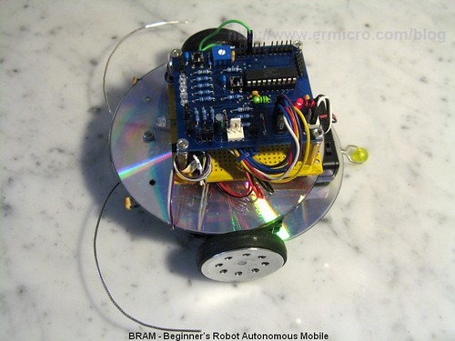
Have you ever thought that most of our perception about the robot is based on the Hollywood movie! The famous 3CPO and R2D2 from Star Wars until the little cute garbage compacting robot named WALL-E; all of these machines are example of our dreams or should I say our quest to what we all think about the robot should be. Although the robot that we are going to build here is still far away from the technologies shown on those movies but at least it will give you an introductory to the robotics world. On this tutorial we will build BRAM which stand for Beginner’s Robot Autonomous Mobile, BRAM construction is designed to be easily built using some of the parts that you could easily found at home, this time we will use Microchip 8-Bits midrange PIC16F690 microcontroller as the BRAM’s brain.
The first autonomous mobile robot is built by William Grey Walter around 1950 at the Burden Neurological Institute in Bristol as part of his research to model brain’s neuron. He built these three wheels robots named ELMER and ELSIE (Electro Mechanical Robot, Light Sensitive) which consists of just two electronic vacuum tubes that represent a simple 2 neurons, remember on those days transistors is just in their earlier stages; these two tube work as two stage amplifier to control a relays that connected to the two DC motors for the robot steering and locomotion.

The steering motor also connected to the photoelectric cell tube sensor and only rotates in one direction. On the dark environment the steering and the driving motor will turn slowly; when the photoelectric cell capture a bright enough light, the steering motor will stop rotate (relay 1 on) and the robot move toward it (light attracted). When the light becomes too bright, the steering motor starts to rotate (relay 2 on) and the robot simply turn away from the light (light avoided). The touch sensor switch is connected to the clear plastic shell (that’s why it’s being called tortoise, because it looks like a tortoise shell) that covered the robot’s body. When the shell bumped to the object, the two stages amplifier will start to oscillate because of the feedback signal generated by the closed touch switch until the robot successfully avoid the obstacle.
Using just a simple electronics neurons model, William Grey Walker is able to show a complex behavior caused by the combination of stimulus (sensors) and the interaction between these two electronics neuron. His works later on inspired many young generation roboticists such as Rodney A. Brooks (subsumption architecture) and Mark Tilden (BEAM) who pioneering a new approach to the robot’s artificial intelligent or known as the nature behavior based artificial intelligent.
BRAM Chassis Construction
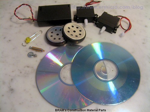
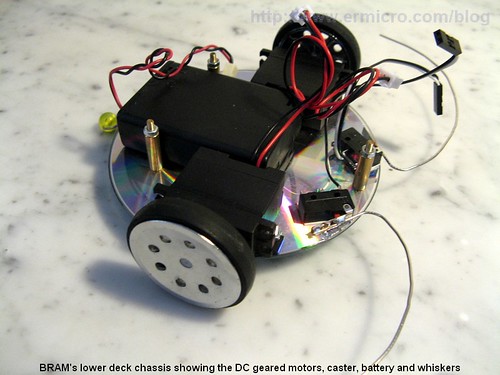
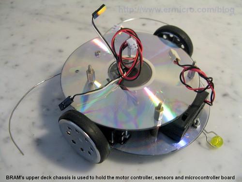
BRAM chassis use two CDs, the lower deck is use to hold the geared DC motor, battery power, caster and the robot’s bumper switches (whiskers) while the upper deck hold the robot’s motor driver, sensor’s board and the PICJazz 16F690 board. The following are the list of BRAM’s construction material parts:
- Two CD/DVDs for the chassis
- Two geared DC motor rated 4.5 to 5 volt with the wheel or you could use the modified servo motor (it’s a servo motor without the electronics’s control board)
- One 3 x 1.5 volt AA battery holder with on-off switch
- One plastic bead (usually it use for the neck less) and one paper clip for the caster
- Two microswitches and two paper clips for the whisker or bumpers sensor (not shown on the above picture).
- Nuts, bolts, PCB (printed circuit board) holders, double tape to hold all of these parts together.
Through these series of the pictures bellow you will get an idea of how to assemble BRAM’s parts; the first two picture show you how to assemble the BRAM’s caster and whisker:
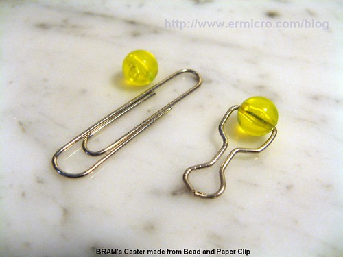

From the above picture you could see that I use a solder’s thin to join the modified paper clip to a microswitch actuator arm; make sure you clean both surfaces with the sand paper first before start soldering them together. What good about the BRAM’s chassis material; its easy to drill (made from polycarbonate plastic) and I bet you have plenty of these unused CD/DVD’s at home or if not just buy a new blank CDs. Bellow is the BRAM’s design drawing I used on this tutorial.
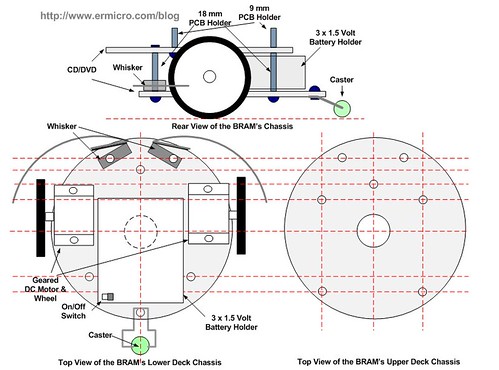
The next two pictures show you how to put all these parts together to the BRAM’s chassis.
BRAM’s Electronic Circuit and Program
What make building the robot is an art; because building a robot is the combination of mechanic, electronic and programming skills, those skills must also be combined with the system control and artificial intelligence knowledge to make a robust and intelligent robot; therefore many years ago this kind of capabilities only reside inside the university labs or highly budget research company.

Today’s with the introduction of cheap sophisticated microcontrollers and sensors the possibility of the amateur roboticists to build an entertaining or perhaps professional robots become widely open; especially with the introduction to the nature base artificial intelligent pioneered by Rodney A. Brooks and Mike Tilden which open a new approach to the mobile robot’s artificial intelligent, programming mobile robot become a reach of amateur roboticists.
Their approach actually is base on the simple question, why such as simple animal likes ant or cockroach could survive in such a very complex nature environment and yet not required a very complex brain? The answer to this question is; because this little creatures use what its called nature behavior based intelligent; unlike the classic approach to artificial intelligent which required a powerful computing power, this new approach make it possible for us to implement it on the 8-bit class microcontroller such as Microchip PIC16F690 microcontroller. This behavior based artificial intelligent model is simply tell us that we develop the robot’s behavior start from the very primitive form such as obstacle avoidance and slowly added a new more complex behavior on top of it.
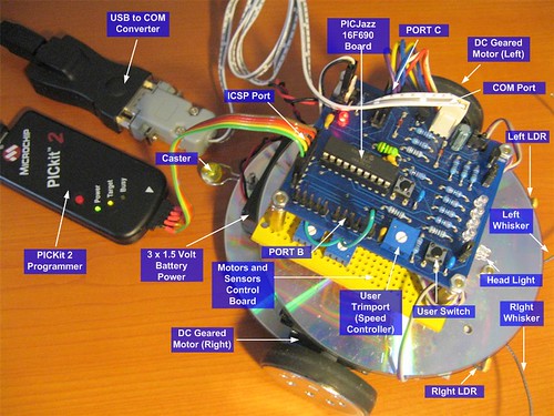
Now take a look at the BRAM’s electronic circuit schematic bellow (for complete schematic of PICJazz 16F690 learning board you could download here and BRAM’s motor controller you could download here):

The DC geared motor is controlled by the two channels SGS-Thomson L293D motor driver chips, this chip is used to make circuit more simpler compared to the standard transistor’s base H-Bridge driver, the L293D chip is able to handle non repetitive current up to 1.2 A for each channels and its already equipped with the internal EMF (Electromotive Force) protection diodes.

The L293D enable input (ENABLE1 and ENABLE2) for both channels is controlled by PWM (Pulse Width Modulation) supplied by the PIC16F690 microcontroller RC3 port which configured as single output PWM , pulse steering mode. For more information about the PIC PWM please refer to my previous posted blog H-Bridge Microchip PIC Microcontroller PWM Motor Controller. The PWM width is controlled by user trimport attached to RA0 port, this make BRAM’s speed could be adjusted (faster or slower) by adjusting this 10K trimport.
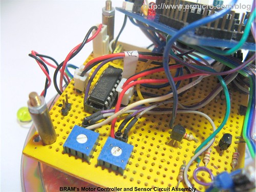
The LDR (Light Dependent Resistor) is use as light sensor, together with the 10K trimport works as the voltage divider circuit to the RC0 and RC1 ADC (Analog to Digital Converter) ports; the voltage supplied to this input will vary according to the light intensity, for more information of how this circuit work please refer to my previous posted blog Basic Servo Motor Controlling with Microchip PIC Microcontroller.
Using the well known R-2R ladder resistor circuit, BRAM’s use this simple 2-bits DAC (Digital to Analog Converter) circuit to read the two bumper switches (whiskers) through the PIC 16F690 microcontroller RC2 ADC port. For more information about the R-2R ladder circuit please refer to my previous posted blog Basic Resistor Circuit. There are two reasons why I am using the DAC circuit to read the switches. The first one, because I am using the output not just for reading the switch status but also use the value to generate random number for the avoidance behavior algorithm, the second one is; I could use just a single ADC microcontroller’s port to read many switches at the same time.
The following is the list of hardware and software used in this tutorial:
- Resistors: 220 Ohm (1), 1K (1), 15K (1), 10 K (2)
- Two LDR (Light Dependent Resistor)
- Two Trimports: 10K
- One White LED for BRAM’s Head Light
- Two Microswitches for the bumper sensors (whikers)
- One Transistor: 2N3904
- PICJazz 16F690 learning board (schematic) from ermicro (build in one user’s trimport and one user’s switch)
- Microchip PICKit2 Programmer
- Microchip MPLAB IDE v8.3 or higher
- HI-TECH C PRO for the PIC10/12/16 MCU family V9.60PL5 (Lite).
Now let’s take a look at the C code that make the BRAM’s brain:
// *****************************************************************************
//  File Name    : brampicphoto.c
//  Version      : 1.0
//  Description  : BRAM - Beginner's Robot Autonomous Mobile
//                 PIC Photovore I
//  Author       : RWB
//  Target       : PICJazz 16F690 Learning Board
//  Compiler     : HI-TECH C PRO for the PIC10/12/16 MCU family V9.60PL5 (Lite)
//  IDE          : Microchip MPLAB IDE v8.30
//  Programmer   : PICKit 2
//  Last Updated : 05 May 2009
// *****************************************************************************
#include <pic.h>
#include <stdlib.h>
#include <stdio.h>
/*   PIC Configuration Bit:
**   INTIO     - Using Internal RC No Clock
**   WDTDIS    - Wacthdog Timer Disable
**   PWRTEN    - Power Up Timer Enable
**   MCLREN    - Master Clear Enable
**   UNPROTECT - Code Un-Protect
**   UNPROTECT - Data EEPROM Read Un-Protect
**   BORDIS    - Borwn Out Detect Disable
**   IESODIS   - Internal External Switch Over Mode Disable
**   FCMDIS    - Monitor Clock Fail Safe Disable
*/
__CONFIG(INTIO & WDTDIS & PWRTEN & MCLREN & UNPROTECT \
  & UNPROTECT & BORDIS & IESODIS & FCMDIS);
// Using Internal Clock of 8 MHz
#define FOSC 8000000L
// Define Light Parameter
#define LIGHT_THRESHOLD  30
#define THRESHOLD_VALUE  50
#define MAX_THRESHOLD    180
// Define BRAM Steering
#define MOVE_FORWARD  0
#define TURN_LEFT     1
#define TURN_RIGHT    2
#define ROTATE_LEFT   3
#define ROTATE_RIGHT  4
#define MOVE_BACKWARD 5
#define FULL_STOP     6
// BRAM Debugging Mode, 0 - Debug Off, 1 - Debug On
#define BRAM_DEBUG    1
#if BRAM_DEBUG
  #define BAUD_RATE 9600
#endif
// Delay Function
#define	_delay_us(x) { unsigned char us; \
			         us = (x)/(12000000/FOSC)|1; \
			         while(--us != 0) continue; }
void _delay_ms(unsigned int ms)
{
  unsigned char i;
  do {
    i = 4;
    do {
      _delay_us(164);
    } while(--i);
  } while(--ms);
}
// BRAM UART Debugging Function
#if BRAM_DEBUG
void ansi_cl(void)
{
  // ANSI clear screen: cl=\E[H\E[J
  putchar(27);
  putchar('[');
  putchar('H');
  putchar(27);
  putchar('[');
  putchar('J');
}
void ansi_me(void)
{
  // ANSI turn off all attribute: me=\E[0m
  putchar(27);
  putchar('[');
  putchar('0');
  putchar('m');
}
void uart_init(void)
{
  TRISB5 = 1;          // Set Port B5 and B7 for UART Tx and Rx
  TRISB7 = 0;
  // Baud Rate formula for SYNC=0 (Async), BRG16=0 (8-bit), BRGH=0 (low speed)
  // 0.16% Error for 8 MHz Oscilator Clock. Actual Rate will be 9615.
  // BAUD_RATE = FOSC / (64 x (SPBRG + 1))

  SPBRG = (int)(FOSC/(64UL * BAUD_RATE)) - 1;
  TXSTA = 0b00100000;  // Async, 8 bit and Enable Transmit (TXEN=1)
  RCSTA = 0b10010000;  // Serial Port Enable, Async,8-bit and Enable Receipt (CREN=1)
  BAUDCTL=0;
}
void putch(unsigned char data)
{
  // Send Data when TXIF bit is ready
  while(!TXIF) continue;
  TXREG = data;
}
unsigned char getch(void) {
  // Get Data when RCIF bit is ready
  while(!RCIF) continue;
  return RCREG;
}
#endif
// BRAM Speed and Steering Functions
void BRAM_speed(unsigned char sp)
{
  // Adjust the PWM CCPR1L register
  CCPR1L=sp;
}
void BRAM_steer(unsigned char steer)
{
  switch(steer) {
    case MOVE_FORWARD:
      RC4=0; RC5=1;  // Right Motor On Forward
      RC6=1; RC7=0;  // Left Motor On Forward
      break;
    case TURN_LEFT:
      RC4=0; RC5=1;  // Right Motor On Forward
      RC6=0; RC7=0;  // Left Motor Off
      break;
    case TURN_RIGHT:
      RC4=0; RC5=0;  // Right Motor Off
      RC6=1; RC7=0;  // Left Motor On Forward
      break;
    case ROTATE_LEFT:
      RC4=0; RC5=1;  // Right Motor On Forward
      RC6=0; RC7=1;  // Left Motor On Reverse
      break;
    case ROTATE_RIGHT:
      RC4=1; RC5=0;  // Right Motor On Reverse
      RC6=1; RC7=0;  // Left Motor On Forward
      break;
    case MOVE_BACKWARD:
      RC4=1; RC5=0;  // Right Motor On Reverse
      RC6=0; RC7=1;  // Left Motor On Reverse
      break;
    case FULL_STOP:
      RC4=0; RC5=0;  // Right Motor Off
      RC6=0; RC7=0;  // Left Motor Off
      break;
  }
}
// BRAM Behaviour Functions
int random_number(void)
{
   unsigned char num;

   num=(unsigned char) rand();
   return ((num % 300) + 20);
}
void BRAM_AvoidMode(unsigned char bump_sensor)
{
  static unsigned char turn_status = 0;
turn_status ^= 0x01;
  // Process the Whisker Sensor
  if (bump_sensor > 50) {
    RA5=1;        // Turn On BRAM Head Light
#if BRAM_DEBUG
    printf("Whisker Value: %d\n\r",bump_sensor);
#endif
    // Initial Random Seed Number
    srand(bump_sensor);

    BRAM_steer(MOVE_BACKWARD);
    _delay_ms(150);
    if (bump_sensor <= 120) {
      // Left Bump Switch Range: 0 to 120
      BRAM_steer(ROTATE_RIGHT);
      _delay_ms(random_number());
    } else if (bump_sensor > 120 && bump_sensor <= 130) {
      // Right Bump Switch Range: 120 to 130
      BRAM_steer(ROTATE_LEFT);
      _delay_ms(random_number());
    } else {
      // Left + Right Bump Switch: > 130
      if (turn_status)
        BRAM_steer(ROTATE_LEFT);
      else
        BRAM_steer(ROTATE_RIGHT);
      _delay_ms(random_number());
    }
  }
}
void BRAM_LightFollow(unsigned char ldr_left, unsigned char ldr_right)
{
  int ldr_diff;
#if BRAM_DEBUG
  printf("Left LDR: %d; Right LDR: %d\n\r",ldr_left,ldr_right);
#endif
  // Get the different
  ldr_diff=ldr_left - ldr_right;
  if ((ldr_diff >= -THRESHOLD_VALUE) && (ldr_diff <= THRESHOLD_VALUE)) {
    if ((ldr_left > MAX_THRESHOLD) || (ldr_right > MAX_THRESHOLD)) {
      // Avoid Light
      BRAM_steer(FULL_STOP);
      _delay_ms(200);
      BRAM_steer(MOVE_BACKWARD);
      _delay_ms(200);
      BRAM_steer(ROTATE_LEFT);
      _delay_ms(200);
    } else {
      BRAM_steer(MOVE_FORWARD);       // Just go straight
    }
  } else {
    if (ldr_diff < 0)
      BRAM_steer(TURN_LEFT);
    else
      BRAM_steer(TURN_RIGHT);
  }
}
void main(void)
{
  unsigned char ldr_left;
  unsigned char ldr_right;
  unsigned char speed;
  unsigned char bump_sensor;
  unsigned char halt_status;
OSCCON=0x70; // Select 8 MHz internal clock
  TRISA = 0x03;        // Input for RA0 and RA1
  TRISC = 0x07;        // Set RC0,RC1 and RC2 as input others as Output
  ANSEL = 0x71;        // Set PORT AN0, AN4, AN5 and AN6 as analog input
  ANSELH = 0x00;       // Set PORT AN8 to AN11 as Digital I/O
  PORTC = 0x00;        // Turn Off all PORTC
  /* Init PWM for Single Output */
  CCP1CON=0b00001100;  // Single PWM mode; P1A, P1C active-high; P1B, P1D active-high
  CCPR1L=0;            // Start with zero Duty Cycle
  PSTRCON=0b00000100;  // Enable PIC Pulse Steering PWM on RC3 Port
  T2CON=0b00000101;    // Postscale: 1:1, Timer2=On, Prescale = 1:4
  PR2=0x65;            // Frequency: 4.90 kHz
  TMR2=0;              // Start with zero Counter

  /* Init ADC */
  ADCON1=0b00110000;   // Select the FRC for 8 MHz
  halt_status=0;       // Initial: 0-Stop, 1-Run
  speed=0;             // Initial Speed
#if BRAM_DEBUG
  // Initial PIC16F690 UART
  uart_init();
  // Set the Attribute and Clear Screen
  ansi_me();
  ansi_cl();
  printf("Welcome to BRAM Debugging Mode\n\r\n\r");
#endif
  // Blink BRAM's Head Light Twice for Ready
  RA5=1; _delay_ms(100);
  RA5=0; _delay_ms(100);
  RA5=1; _delay_ms(100);
  RA5=0; _delay_ms(100);

  for(;;) {
    if (RA1 == 0) {           // BRAM Status Switch
      _delay_ms(1);
      if (RA1 == 0) {         // Read again for Simple Debounce
        halt_status ^= 0x01;  // Halt Status
      }
    }
    /* Start Read All the ADC input here */
    // The PWM Motor Speed Control
    ADCON0=0b00000001;        // Select Left justify result. ADC port channel AN0
    GODONE=1;	              // Initiate conversion on the channel 0
    while(GODONE) continue;   // Wait for conversion done
    speed=ADRESH;
    // Bumped Sensor
    ADCON0=0b00011001;       // Select left justify result. ADC port channel AN6
    GODONE=1;	             // Initiate conversion on the channel 6
    while(GODONE) continue;  // Wait for ldr_left conversion done
    bump_sensor=ADRESH;      // Read 8 bits MSB, Ignore 2 bits LSB in ADRESL

    // The LDR Sensor
    ADCON0=0b00010001;       // Select left justify result. ADC port channel AN4
    GODONE=1;	             // Initiate conversion on the channel 4
    while(GODONE) continue;  // Wait for ldr_left conversion done
    ldr_left=ADRESH;         // Read 8 bits MSB, Ignore 2 bits LSB in ADRESL
    ADCON0=0b00010101;       // Select left justify result. ADC port channel AN5
    GODONE=1;	             // Initiate conversion on the channel 5
    while(GODONE) continue;  // Wait for ldr_right conversion done
    ldr_right=ADRESH;        // Read 8 bits MSB, Ignore 2 bits LSB in ADRESL

    // BRAM Steering Speed
    BRAM_speed(speed * halt_status);
    RA5=0;                   // Turn Off BRAM Head Light
    // Whisker Sensor
    BRAM_AvoidMode(bump_sensor);

    // Light Follower
    BRAM_LightFollow(ldr_left,ldr_right);
    _delay_ms(10);
  }
}
/* EOF: brampicphoto.c */
Downloading the Code
After compiling and simulating your code hook up your PICKit2 programmer to the PICJazz 16F690 board ICSP port turn the PICJazz 16F690 power. From the MPLAB IDE menu select Programmer -> Select Programmer -> Pickit2 it will automatically configure the connection and display it on the PICkit 2 tab output windows; Now you are ready to down load the code from MPLAB IDE menu select Programmer -> Program; this will down load the HEX code into the PICJazz 16F690 board:
Now you could enjoy BRAM with its basic obstacle avoidance and light following (photovore) behaviors:
The Final Thought
As shown by William Grey Walter with his tortoise robot, BRAM’s also show some kind of intelligent which is quite entertaining especially for my kids as they start to build their own maze and see how BRAM could solve that maze. On the second part of this tutorial we will explore more detail of the BRAM’s brain and how we utilize Microchip PIC 16F690 microcontroller UART peripheral for debugging BRAM.
Bookmarks and Share


Related Posts
12 Responses to “Building BRAM your first Autonomous Mobile Robot using Microchip PIC Microcontroller – Part 1”
Comment by rwb.
Thanks, the L293D driver controller is designed to work up to max 36 volt, you could easily drive 12 volt geared motor by supplying the 12 volt to the Vs pin (Supply Voltage/Motor Supply pin) while keep the 4.5 volt on the Vss pin (Logic Supply Pin). For the PICJazz 16F690 PCB, currently we not publish it to the public; only the schematic which you could download from this blog.
Comment by neyo_napster.
Thanks a lot!!!
Comment by Eric88.
can you please provide me the assembler code that make the BRAM’s brain?? thanks
Comment by anotech.
sir, i hav to do a line following robot with these ICs,
L293D
PIC 16f877A
so i want the circuit diagram to make it, can u please help me.
i want the diagram with the connecting port (to programme)can you…………………….
Comment by anotech.
…link removed…
will this programmer help me to program PIC 16f877A ic???
so my line following robot moves knw?
Comment by rwb.
You could learned the principle of how the microcontroller based LFR work on this following article:
Build Your Own Microcontroller Based PID Control Line Follower Robot (LFR) – Second Part
About the Microchip PIC16F877A programmer, my recommendation is to use the Microchip PICKit 2 or PICKit 3 programmer.
Comment by Tec321.
I like it so much.
I was wondering if I Could ask you about the wheels and DC motor, what is the specific name of the DC motor and the wheels that were used in this project?
Comment by rwb.
You could experiment with any DC geared motor or you could use the Solarbotic GM2 DC geared motor.
Comment by Tec321.
One more question, you have used 8MHz crystal, am I right?

Comment by neyo_napster.
awesome work!!!
can u please provide the PCB layout of the PICJAZZ board.and how can we modify the circuit to drive a 12V dc geared motor?
mail: neyo_napster@yahoo.com