Blog Entry
Seven Segment Display Thermometer with PIC Microcontroller
March 8, 2009 by rwb, under Microcontroller.
The seven segment display is one of the most popular numeric displays used in many microcontroller applications because it’s cheap, robust and reliable. The seven segments actually consists of 8 LED (Light Emitting Diode) and it’s come with various sizes suitable for various numeric display application such as digital clock, counter, thermometer, humidity, etc. On this project we are going to show you how to drive this type of display and this time we will use the Microchip PIC16F886 microcontroller to display the room’s temperature both in Centigrade and Fahrenheit scale.
The Seven Segments Display
Many years ago before the LCD (Liquid Crystal Display) come into the arena, the seven segments display is the main player; it’s so popular and its use in almost everything not just to display the numeric value but also a character as well, such as my old Multitech Zilog Z80 microprocessor teaching board to run the BASIC language interpreter bellow:
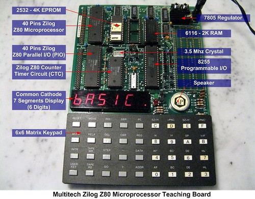
From the above picture you could see how complex the circuit was on those days; the circuit consists of separate IC such as 8-bit microprocessor (Zilog Z80), counter timer circuit (CTC), 4K EPROM (Erasable Programmable ROM, this ROM type can be erased only by exposing it to the UV lamp) for the firmware (the board basic I/O function and BASIC language interpreter), 2K RAM for the program and the I/O controller. Thanks to today technology this complex circuit is already put into single chip known as the microcontroller and we don’t have to use this UV lamp to erase the program anymore (you must be laugh right know, but on those days that’s the only way to do it) but what remain the same is; we still use this seven segments display, mostly for displaying the numeric value.
There are two types of seven segments available on the market known as common anode (CA) and common cathode (CC):

Displaying the seven segments is just a matter of applying the correct forward bias voltage to each of the LED’s segment in the seven segments package; for example if we want to show the digit “3” than we have to apply the forward bias voltage on each of the A, B, C, D and G LED segments. The segment pins out is vary among the types and the brands, therefore you have to find out the correct pins for each segments and the common pin as well before you can start to use it.
The Room’s Temperature Project
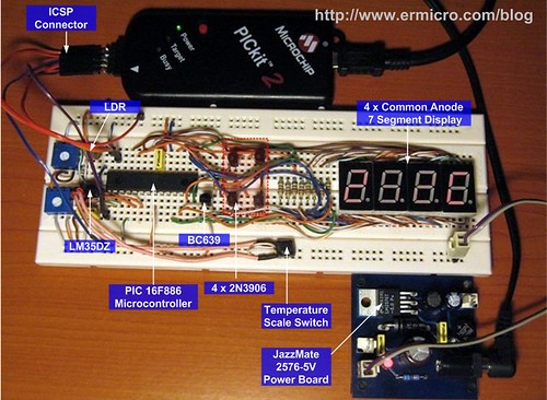
Our room’s temperature project is use 4 seven segments display for displaying the room’s temperature. The heart of this room’s temperature project is the 8-bit 28 pins midrange Microchip PIC16F886 microcontroller (for those with the Atmel AVR background this microcontroller is comparable to the AVR ATMega8 or ATMega88 microcontroller families). The following is the complete schematic design for this project:

The designed I’ve made here not solely to show the room’s temperature with the seven segments, but it serve as the good learning tools as well, as we will explore the PIC 16F886 features such as ADC (Analog to Digital Converter), PWM (Pulse Width Modulation) and the timer counter capabilities in one shoot. Ok now lets fasten your seat belt as we will run through the design concept here.
First is the display, all the common anode seven segments are connected to PIC 16F886 microcontroller’s port RC0 to RC7, because the microcontroller’s port I/O could not sink the 8 LEDs current all together so we use the 2N3906 PNP transistor (T1 to T4) to sink the current; you could read more about sinking and sourcing I/O port in Powering Your Microcontroller Project article posted on this blog. Differ from usual design I put the NPN BC639 transistor (T5) for driving the four PNP transistors (T1 to T4) with the PWM signal in order to control the seven segments display contrast.

The display contrast is controlled by the LDR (light dependent resistor) together with 10K trimpot serve as the voltage divider input to the PIC16F688 microcontroller analog port AN1; by detecting the light intensity captured by the LDR, this room’s temperature circuit will automatically adjust the seven segments display contrast according to the room’s light intensity. The darkest the room’s the brightest the seven segments display and vise verse.
Secondly the temperature sensor, on this circuit we use the National Semiconductor LM35DZ precision centigrade temperature sensor. The LM35DZ will produce linear voltage output of 10 mV for each degree of the temperature increment in centigrade scale. Together with the 1 Volt voltage reference input provided by 10K trimpot (R17) on the PIC16F886 microcontroller’s VRef+ (4) and VRef- (5) pins, we could precisely measure the room’s temperature on the PIC16F886 microcontroller’s analog port AN0.
The last is the S1 switch, this switch is use as the toggle switch to choose the room’s temperature scale: Centigrade or Fahrenheit. The following table shows the Microchip PIC16F886 microcontroller ports used in this project:


The following is the list of hardware and software used in this tutorial:
1. Resistor: 680 Ohm (8), 4K7 (4), 2K7 (1), 10 K (1)
2. Two Trimpot: 10 K
3. One LDR (Light Dependent Resistor)
4. Capacitor: 100nF (1), 10nF (1)
5. One Micro Switch
6. Transistor: NPN BC639 (1), PNP 2N3906 (4)
7. National Semiconductor LM35DZ precision centigrade temperature sensor (TO-92)
8. 4 Common Anode Seven Segments Display
9. Microchip PIC16F886 Microcontroller
10. Microchip PICKit2 Programmer
11. Microchip MPLAB IDE v8.0 or higher
12. HI-TECH C PRO for the PIC10/12/16 MCU family V9.60PL5 (you could not use the HI-TEC PICC Lite version on the Microchip PIC 16F886 microcontroller, but you could use the Hi-TECH C PRO in Lite Mode).
Now let’s take a look at the C code that makes this thing happen:
// ***************************************************************************
//  File Name    : pictemp.c
//  Version      : 1.0
//  Description  : PIC Thermometer
//  Author       : RWB
//  Target       : Microchip PIC16F886 Microcontroller
//  Compiler     : HI-TECH C PRO for the PIC10/12/16 MCU family V9.60PL5
//  IDE          : Microchip MPLAB IDE v8.00
//  Programmer   : PICKit2
//  Last Updated : 28 Feb 2009
// ***************************************************************************
#include <pic.h>
/*   PIC Configuration Bit:
**   INTIO      - Using Internal RC No Clock
**   WDTDIS     - Wacthdog Timer Disable
**   PWRTEN     - Power Up Timer Enable
**   MCLRDIS    - MCLR functions as IO
**   UNPROTECT  - Code Un-Protect
**   DUNPROTECT - Do not read protect EEPROM data
**   BORDIS     - Brown Out Detect Disable
**   IESODIS    - Internal External Switch Over Mode Disable
**   FCMDIS     - Monitor Clock Fail Safe Disable
**   BORV21     - Brown Out Reset 2.1 Volt
*/
__CONFIG(INTIO & WDTDIS & PWRTDIS & MCLRDIS & UNPROTECT & DUNPROTECT & \
  BORDIS & IESOEN & FCMDIS & LVPDIS & DEBUGEN);   // Address 0x2007
__CONFIG(BORV21);                                 // Address 0x2008
// Using Internal Clock of 8 MHz
#define FOSC 8000000L
// Variable Used for Thermometer
#define LDR_THRESHOLD 50
#define MAX_DCYCLE 255
const char SSEG[] = {
  0b11000000,  // 0, LED Segment: A,B,C,D,E,F
  0b11111001,  // 1, LED Segment: B,C
  0b10100100,  // 2, LED Segment: A,B,D,E,G
  0b10110000,  // 3, LED Segment: A,B,C,D,G
  0b10011001,  // 4, LED Segment: B,C,F,G
  0b10010010,  // 5, LED Segment: A,C,D,F,G
  0b10000010,  // 6, LED Segment: A,C,D,E,F,G
  0b11111000,  // 7, LED Segment: A,B,C
  0b10000000,  // 8, LED Segment: A,B,C,D,E,F,G
  0b10010000,  // 9, LED Segment: A,B,C,D,F,G
  0b11000110,  // C, LED Segment: A,D,E,F
  0b10001110   // F, LED Segment: A,E,F,G
};
unsigned char DispDigit[4];
unsigned char DigitCount;
unsigned char TempType;
static void interrupt isr(void)
{
  if(T0IF) {			    // TIMER0 Interrupt Flag
    /* Pull Low the Segment */
    PORTC = DispDigit[DigitCount];
    /* Activate the Digit and Advanced to next Digit */
    PORTB = ~(1 << DigitCount++);

    /* Reset the Digit Count */
    if (DigitCount > 3)
      DigitCount=0;

    TMR0 = 156;             // Initial Value for 3.2 ms Interrupt
    T0IF = 0;			    // Clear TIMER0 interrupt flag
  }
}
// Delay Function
#define _delay_us(x) { unsigned char us; \
	  	       us = (x)/(12000000/FOSC)|1; \
		       while(--us != 0) continue; }
void _delay_ms(unsigned int ms)
{
  unsigned char i;
  do {
    i = 4;
    do {
      _delay_us(164);
    } while(--i);
  } while(--ms);
}
/* Seven Segment Put Number: Implementing floating value from 0 to 99.9 */
void SSEG_putnum(float number)
{
   unsigned char iDigit,iDigit1,iDecimal;
if (number > 99.9) return;
   /* Global interrupt disable */
   GIE = 0;

   iDigit=number;                        // Convert float to Integer
   iDecimal=(number - iDigit) * 10;      // Get The Decimal Digit
   DispDigit[1]=SSEG[iDecimal];          // First Decimal Digit
   if (iDigit >= 10) {
     iDigit1=iDigit / 10;
     DispDigit[3]=SSEG[iDigit1];         // Second Digit
     iDigit=iDigit - (iDigit1 * 10);
   } else {
     DispDigit[3]=SSEG[0];               // Zero Sign Second Digit
   }
   DispDigit[2]=SSEG[iDigit] & 0x7F;     // First Digit with Decimal Point
   /* Global interrupt enable */
   GIE = 1;
}
void main(void)
{
  unsigned int iValue,iCTemp;
  unsigned char ldr_value;
  float CentTemp;

  OSCCON=0x70;         /* Select 8 MHz internal clock */

  TRISA = 0xFF;        // Input for RA0 to RA7
  TRISB = 0x00;        // Output for RB0 to RB7
  TRISC = 0x00;        // Output for RC0 to RC7
  ANSEL = 0b00000011;  // Set PORT AN0 and AN1 to analog input AN2 to AN7 digital I/O
  ANSELH = 0b00000000; // Set Other as Digital I/O
  /* Initial Output Port */
  PORTC=0xFF;
  PORTB=0xFF;
  /* Init TIMER0: Period: 1/(Fosc/4) x Prescaler x TMR0
     0.0005 ms x 64 * 100 = 3.2 ms */
  OPTION = 0b00000101; // 1:64 Prescaler
  TMR0=156;            // Interrupt every 3.2 ms
  T0IE = 1;	       // Enable interrupt on TMR0 overflow
  GIE = 1;	       // Global interrupt enable
  /* Init PWM for Single Output */
  CCP1CON=0b00001100;  // Single PWM mode; P1A, P1C active-high; P1B, P1D active-high
  CCPR1L=MAX_DCYCLE;   // Start with Max Duty Cycle
  T2CON=0b00000101;    // Postscaler: 1:1, Timer2=On, Prescaler = 1:4
  PR2=0x65;            // Frequency: 4.90 kHz
  TMR2=0;              // Start with zero Counter
  PSTRCON=0b00001000;  // Enable Pulse Steering on P1D (RB4)
  /* Initial variables used */
  DigitCount=0;
  TempType=0;                // Centigrade Type
  DispDigit[0]=SSEG[10];     // Centigrade Sign
  DispDigit[1]=SSEG[0];      // Zero Digit
  DispDigit[2]=SSEG[0];      // Zero Digit
  DispDigit[3]=SSEG[0];      // Zero Digit
  for(;;) {
    /* Get First Sample */
    ADCON0=0b11000001;       // Select the FRC for 8 MHz. ADC port channel 0, Turn On A2D
    ADCON1=0b10110000;       // Right Justified, Vref: VCFG1 and VCFG0 (1 Volt Reference)
    GODONE=1;	             // initiate conversion on the channel 0
    while(GODONE) continue;  // Wait conversion done
    iValue=ADRESL;           // Get the 8 bit LSB result
    iValue += (ADRESH << 8); // Get the 2 bit MSB result
    iCTemp = iValue;
    _delay_ms(50);
    /* Get Second Sample */
    GODONE=1;	// initiate conversion on the channel 0
    while(GODONE) continue;  // Wait conversion done
    iValue=ADRESL;           // Get the 8 bit LSB result
    iValue += (ADRESH << 8); // Get the 2 bit MSB result
    iCTemp += iValue;
    _delay_ms(50);
    /* Get Third Sample */
    GODONE=1;	// initiate conversion on the channel 0
    while(GODONE) continue;  // Wait conversion done
    iValue=ADRESL;           // Get the 8 bit LSB result
    iValue += (ADRESH << 8); // Get the 2 bit MSB result
    iCTemp += iValue;

    /* Calculate the Average Centigrade Value */
    /* (ADC Value/10.24) / Vref, LM35DZ Out=10mV/C, Vref = 1 Volt */
    CentTemp=(iCTemp/3.0)/ 10.24;
    /* Read the Light Sensor */
    ADCON0=0b11000101;       // Select the FRC for 8 MHz. ADC port channel 1, Turn On A2D
    ADCON1=0b00000000;       // Left Justified, Vref: Vss and Vdd
    GODONE=1;	             // initiate conversion on the channel 0
    while(GODONE) continue;  // Wait conversion done
ldr_value = ADRESH; // Get the LDR Value, Ignore the LSB on ADRESL
    if (ldr_value > LDR_THRESHOLD)
     ldr_value = LDR_THRESHOLD;
CCPR1L=MAX_DCYCLE - (5 * ldr_value); // Set the PWM Duty Cycle
    /* Read the RA4 Switch */
    if (RA4 == 0) {              // Change the Thermometer Type when pressed
      _delay_ms(1);
      if (RA4 == 0) {            // Read again for Simple De bounce
        TempType=~TempType;      // Change Type Flag
      }
    }
    /* Set the Temperature Type */
    if (TempType) {
      /* Fahrenheit = 9/5 x Centigrade + 32 */
      CentTemp=((9.0/5.0) * CentTemp) + 32;
      DispDigit[0]=SSEG[11];     // Fahrenheit Sign
    } else {
      DispDigit[0]=SSEG[10];     // Centigrade Sign
    }

    /* Now Display The Result */
    SSEG_putnum(CentTemp);
    _delay_ms(200);
  }
}
/* EOF: pictemp.c */
Multiplexing with PIC TIMER0
As you’ve seen from the schematic above, displaying the entire seven segments digits at the same time would be not possible because every digit will have different information to be displayed, in other word every digit will display different LED segment combination; therefore the solution is to display it one at the time. If we display the four seven segment digits in sequence fast enough, it will appear (give an illusion) to our eyes as we display all these segments simultaneously; this method is called multiplexing.

The multiplexing algorithm is best implemented using the PIC timer/counter TIMER0 peripheral; by letting the TMR0 counter register to overflow and generate interrupt every 3.2 ms, we could display each of the seven segments digit every 3.2 ms; the total time to complete displaying the whole digits is about 12.8 ms (4 x 3.2ms) and this time is already sufficient to avoid flicking appear to our eyes (you could read more about PIC TIMER0 peripheral on the Basic Servo Motor Controller with Microchip PIC Microcontroller article posted on this blog).
The following is the C code that implements this algorithm:
const char SSEG[] = {
  0b11000000,  // 0, LED Segment: A,B,C,D,E,F
  0b11111001,  // 1, LED Segment: B,C
  0b10100100,  // 2, LED Segment: A,B,D,E,G
  0b10110000,  // 3, LED Segment: A,B,C,D,G
  0b10011001,  // 4, LED Segment: B,C,F,G
  0b10010010,  // 5, LED Segment: A,C,D,F,G
  0b10000010,  // 6, LED Segment: A,C,D,E,F,G
  0b11111000,  // 7, LED Segment: A,B,C
  0b10000000,  // 8, LED Segment: A,B,C,D,E,F,G
  0b10010000,  // 9, LED Segment: A,B,C,D,F,G
  0b11000110,  // C, LED Segment: A,D,E,F
  0b10001110   // F, LED Segment: A,E,F,G
};
unsigned char DispDigit[4];
unsigned char DigitCount;
if(T0IF) {		      // TIMER0 Interrupt Flag
  /* Pull Low the Segment */
  PORTC = DispDigit[DigitCount];
  /* Activate the Digit and Advanced to next Digit */
  PORTB = ~(1 << DigitCount++);

  /* Reset the Digit Count */
  if (DigitCount > 3)
    DigitCount=0;

  TMR0 = 156;             // Initial Value for 3.2 ms Interrupt
  T0IF = 0;		  // Clear TIMER0 interrupt flag
}
The seven segments LED display is store in the SSEG[] constant array, therefore by assigning this array to the PIC16F886 microcontroller’s PORT C (RC0 to RC7), the corresponding LED’s segment on the seven segments display will be pulled to the ground (low), and by pulling low the corresponding PNP transistor (T1 to T4) base lead attached to the PORT B, we could make the seven segment to display it’s content.
The TIMER0 is initialized by choosing the 64 prescaler on the OPTION register and preset the TIMER0 counter register TMR0 to 156 will ensure that it will always overflow every 3.2 ms. Using the 8 MHz internal clock frequency, we could calculate the TIMER0 period with this following formula:
TIMER0 Period = 1/(Fosc/4) x Prescale x (256 – TMR0)
TIMER0 Period = 0.0005ms x 64 x (256 – TMR0) = 3.2 ms
Bellow is the complete C code for initializing this PIC TIMER0 peripheral:
/* Init TIMER0: Period: 1/(Fosc/4) x Prescaler x TMR0
     0.0005 ms x 64 * 100 = 3.2 ms */
OPTION = 0b00000101; // 1:64 Prescale
TMR0=156;            // Interrupt every 3.2 ms
T0IE = 1;            // Enable interrupt on TMR0 overflow
GIE = 1;	     // Global interrupt enable
Reading the Temperature
The room’s temperature is base on the voltage level output supplied by the LM35DZ sensor, this precision centigrade temperature sensor from National Semiconductor is connected to the PIC16F886 microcontroller’s analog port AN0.

In order to get the precision ADC result on the PIC16F886 microcontroller, we use the 10 K trimpot (R17) to supply the 1 volt external voltage reference to the microcontroller’s successive approximately circuit. Make sure you adjust this trimpot so the voltage across VRef+ (Pin 5) and VRef- (Pin 4) is measured approximately 1 volt, this is the first important step after you complete building this project. The ADC peripheral on the PIC16F886 in general is similar to the PIC16F690 (you could read more information about the PIC ADC on the PIC Analog to Digital C Programming article posted on this blog); there are only minor different on setting the ADCON0 and ADCON1 registers (for more information please refer to the Microchip PIC16F886 microcontroller datasheet).

Because we are using the internal clock (FRC) of 8 MHz, then we set these ADC clock selection bits to ADCS1 = 1 and ADCS0 = 1. The channel selection bits CHS3, CHS2, CHS1 and CHS0 is used to select the appropriate analog channel input where on this project we use 2 analog inputs, one for the temperature sensor (AN0) and the other for the light intensity sensor (AN1).

The 10-bit analog to digital conversion result format in ADRESH and ADRESL registers is determined by the ADFM bit on the ADCON1 register, by setting this bit to “0” the result will be left justified, this mean the first 8-bit MSB bits will be placed on the ADRESH register while the last 2-bit LSB bits will be placed on the ADRESL register. Assigning ADFM bit to “1” make the 10-bit ADC peripheral to put the first 2-bit MSB result on the ADRESH register and the last 8-bit result will be placed on the ADRESL register (right justified result).
The voltage reference bits VCFG1 and VCFG2 is use to select the voltage reference for the ADC peripheral circuit; when we use the PIC16F886 microcontroller’s ADC peripheral circuit to read the room’s temperature we use the 1 volt external voltage reference, therefore we set the VCFG1 and VCFG0 bits to “1“; and when we use it for reading the light intensity we set these voltage reference bits to “0” (use the Vdd as the voltage reference). The following is the C code for setting the PIC 16F886 microcontroller’s ADC peripheral:
ADCON0=0b11000001;  // Select the FRC for 8 MHz. ADC port channel 0, Turn On A2D
ADCON1=0b10110000;  // Right Justified, Vref: VCFG1 and VCFG0 (1 Volt Reference)
The 10-bit ADC result could be calculated using this following formula:
ADC Result = (Vin x 1024) / VRef
With the 10 mV linear increment for every Centigrade increment of the room temperature starting from zero, than the 100 Centigrade degree room’s temperature with 1 volt external voltage reference could be calculated as follow:
ADC result = (Vin x 1024) / VRef = (100 x 10mV x 1024)/1 = 1024
Dividing the result by 10.24, we could get the exact reading of 100 on Centigrade scale. Using the following Centigrade to Fahrenheit conversion formula bellow we could easily convert the scale from Centigrade to the Fahrenheit scale:
Fahrenheit Scale = 9/5 x Centigrade Scale + 32
The PWM Controlled Display
One of my favorite features on this project is the ability to automatically control the brightness of the seven segments display according to the room’s light intensity; this feature make this circuit to use low power consumption by dimming the seven segment’s LED on the bright light room and brighten the seven segment’s LED on the complete darkness.

The heart of this feature is the PIC16F886 microcontroller single output PWM mode (you could read more about PIC PWM on the H-Bridge Microchip PIC Microcontroller PWM Motor Controller article posted on this blog), the PWM signal is feed to the base lead of T5 transistor (BC639) which supply the current needed by the seven segments driver transistors T1 to T4 (2N3906). By making lower PWM duty cycle the T5 transistor will conduct less, this will make the T1 to T4 transistors supply less current to the seven segments and as the result the LEDs will dim. Bellow is the PIC PWM peripheral initialization C code:
#define MAX_DCYCLE 255
/* Init PWM for Single Output */
CCP1CON=0b00001100;  // Single PWM mode; P1A, P1C active-high; P1B, P1D active-high
CCPR1L=MAX_DCYCLE;   // Start with Max Duty Cycle
T2CON=0b00000101;    // Postscale: 1:1, Timer2=On, Prescale = 1:4
PR2=0x65;            // Frequency: 4.90 kHz
TMR2=0;              // Start with zero Counter
PSTRCON=0b00001000;  // Enable Pulse Steering on P1D (RB4)
The LDR (Light Dependent Resistor) and the trimport circuit is called voltage divider circuit (you could read more about the voltage divider circuit on the Basic Resistor Circuit article posted on this blog), this circuit simply provide the voltage level to the AN1 analog input channel; more light received by the LDR the higher the voltage level input to the AN1 port and vice verse.
Therefore by connecting the ADC result from AN1 channel to the PWM duty cycle, we could achieve this behavior as shown on this C code bellow:
#define LDR_THRESHOLD 50
#define MAX_DCYCLE 255
/* Read the Light Sensor */
ADCON0=0b11000101;     // Select the FRC for 8 Mhz. ADC port channel 1, Turn On A2D
ADCON1=0b00000000;     // Left Justified, Vref: Vss and Vdd
GODONE=1;	         // initiate conversion on the channel 0
while(GODONE) continue;  // Wait conversion done
ldrvalue=ADRESH;         // Get the LDR Value, Ignore the LSB on ADRESL
if (ldr_value > LDR_THRESHOLD)
  ldrvalue=LDR_THRESHOLD;
CCPR1L=MAX_DCYCLE - (5 * ldr_value); // Set the PWM Duty Cycle
As you notice from the code that we are not directly assign the ADC result on the ADRESH register to the CCPR1L register which control the PWM duty cycle output; this is due to the behavior we required; that the more light intensity received by the LDR the more higher the ADC value result we’ve got but on the other hand we have to assign less PWM duty cycle value and vice verse.
Inside the C Code
Differ from the Microchip PICF6F690, the PIC16F886 microcontroller has two configuration bit words; one is located on the address 0x2007 and the other on the address 0x2008. Although we disable the brown out detection on this project (BORDIS) but is a good practice to put these two configuration bits words in your program:
__CONFIG(INTIO & WDTDIS & PWRTDIS & MCLRDIS & UNPROTECT & DUNPROTECT & \
  BORDIS & IESOEN & FCMDIS & LVPDIS & DEBUGEN);   // Address 0x2007
__CONFIG(BORV21);                                 // Address 0x2008
As you see from the statement, there is no configuration bit address specified on the code, but the HITEC-C PRO compiler is smart enough to place the BORV21 (brown out reset at 2.1 volt) configuration bit to the correct address 0x2008.
The program begin by initialized the PIC16F886 microcontroller’s ports needed by this project and continue with the PIC peripheral initialization routine. Next the program entering the infinite loop where inside this loop the program will do these following tasks:
- First we read the room’s temperature from the analog channel 0 three times and get the average result
- Secondly we read the room’s light intensity from the analog channel 1 and use the value to properly adjust the PWM duty cycle for the display contrast
- Third we read the switch and doing the Centigrade to Fahrenheit scale conversion as needed.
- At last we display the room’s temperature value by calling the SSEG_putnum() function; this function work by separating the numeric value digits and assign each digit to the corresponding DispDigit[] array variable using the appropriate seven segment constant SSEG[] array definition. Next the PIC TIMER0 interrupt function will use the DispDigit[] array variable and DigitCount variable for multiplexing the output through PIC16F886 microcontroller’s PORTC and PORTB.
Downloading the Code
After compiling and simulating your code hook up your PICKit2 programmer to the board ICSP connector (in this project I use the breadboard). From the MPLAB IDE menu select Programmer -> Select Programmer -> Pickit2 it will automatically configure the connection and display it on the PICkit2 tab Output windows:


Now you are ready to down load the code from MPLAB IDE menu select Programmer -> Program; this will down load the HEX code into the Microchip PIC 16F886 Microcontroller:
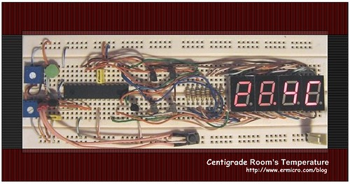
Now just relax and enjoy your room’s temperature project in action:
The Final Thought
If you build this project using the breadboard (as I did), with your creativity and imagination you could transform this project as the work of art by putting the breadboard inside the nice photo frame and hang it on the wall or perhaps putting on your desk. Share it to your friends and let them enjoy the electronics art as well as the fully functioning room’s temperature with the light sensor, who knows they might be interest to buy this piece of art from you; of course if you willing to sell it. Just to give you a clue to what I mean, take a look on this possible looks of your room’s temperature project:
Bookmarks and Share


Related Posts
117 Responses to “Seven Segment Display Thermometer with PIC Microcontroller”
Comment by pichaha.
Hi,
If I am using servo motor and I want to multiplex seven segment displays as well…how am I going to allocate the timer0?? I am thinking of using timer0 and timer1 simultaneously but I think this will trigger contradiction…or I just assign everthing in the timer0 routine is that possible…thanks a lot.
Comment by rwb.
Yes you could use both Microchip PIC16F886 microcontroller TIMER0 (8-bit) and TIMER1 (16-bit) and even TIMER2 (8-bit) peripherals at the same time.
Comment by pichaha.
Hi,
I would like to ask, beside using timer0 for displaying seven segment…what other type of technique can i use?…actually I have tried to display them by normal codes in the main function…it works, but not clear and unstable…thanks a lot.
Comment by rwb.
Basically you could use any of the Microchip PIC TIMER peripherals to do the Seven Segment multiplexing.
Comment by pichaha.
Yes, I have tested it using other timer interrupt and it works very well, thanks a lot…I have another question here…actually I want to optimize the usage of every single pin in pic16f690…and if I am not using the dot pin in the seven segment, from the seven segment array in your source codes (SSEG[]), how am I going to use that particular pin (the pin that suppose to connect to the dot pin) for other output purpose?
Comment by rwb.
Sure you can do it. As a rules of thumb when designing the microcontroller circuit you need to consider the efficiency of the C code for driving this circuit as well. Sometimes we have to change the circuit design in order to get more efficient C code. In your case it is depend of how you will use the RC7 output (the seven segment DOT pin in this project) e.g. blink LED, driving motor, activating relay, servo, etc; as this will change this following C statement in the interrupt service routine:
PORTC = DispDigit[DigitCount];
Comment by pichaha.
I am using that for buzzer…from your reply you mean I need to change the structure of the array or I can just apply some coding technique to modify it…I am only using RC0 to RC6
Comment by pichaha.
Sorry I still haven’t finished…I am only using RC0 to RC6 for seven segments…but in the array, I have to assigned value for RC7 as well…I mean what is the approach as we cannot assign only 7 numbers for PORTC, like PORTC = 0b0001111, the 8th bit just ignore it, impossible right?
Please help thanks a lot
Comment by rwb.
You could simply use a C mask operator to the PIC microcontroller PORTC as follow:
BUZZER=0x7F; // Turn Off Buzzer
PORTC = DispDigit[DigitCount] & BUZZER;
and
BUZZER=0xFF; // Turn On Buzzer
PORTC = DispDigit[DigitCount] & BUZZER;
Comment by pichaha.
Hi, your method is really great..i never think that before haha…btw I am curious how are you going to drive servo using that pin?
Comment by pichaha.
Sorry I mean not using your method in your servo article…I mean use the pwm feature in the mcu…thanks a lot…
Comment by rwb.
You could not use the Microchip PIC16F690 PWM peripheral on RC7! First, not all the Microchip PIC16F690 pins could be assigned as PWM peripheral output, for more information please read “H-Bridge Microchip PIC Microcontroller PWM Motor Controller” article on this blog. Secondly if we use the PWM peripheral to drive the servo motor it means we have to lower the PIC16F690 operating frequency please read “Basic Servo Motor Controlling with Microchip PIC Microcontroller” article.
Comment by pichaha.
Yes, I know…I mean how to utilize different port pins to multiplex seven segment…because I need P1A pin to drive servo, but I have solved the problem using your idea(using logical operators), and it worked for multiplexing seven segments for different port pins…I have tried your method to drive servo as well and it worked but I would like to try with the pwm feature in the mcu…I have tried to drive the servo (only servo in my circuit), it can turn clockwise and counter clockwise. I can turn it in small degree as well by gradually increase the bit in CCPR1L&CCP1CON automatically in a FOR loop, but when it comes to control the degree increment using push button, it becomes very unstable, the voltage from my voltage regulator will suddenly drop down to unusual level…can I know the problem please…if possible can I send you my source codes?? Please help thanks a lot.
Comment by rwb.
There is no relation between the PIC microcontroller C code and the sudden voltage drop of the voltage regulator when you press the push button which effecting the servo motor operation. The voltage regulator should maintain a constant voltage output as long as the operating load is still within its specification limit, that’s why it being called the voltage regulator. You should recheck your circuit.
Comment by pichaha.
OK, thanks a lot…so is it recommended to drive a servo using a 9V battery (maybe energizer)?
Comment by rwb.
Its depend on your application, for remote operation, sure you need a battery such as 9 volt (PP3) to operate your circuit but for permanent location where the electricity is available is cheaper to use the power adapter to provide DC supply to your circuit.

Comment by rwb.
Because you use the same 4 seven segment digit for displaying 3 decimal point then you need to modify the SSEG_putnum() function algorithm so it will assigned 0.000 to 9.999 instead of 00.0C to 99.9C to the DispDigit[4] array variables