Blog Entry
H-Bridge Microchip PIC Microcontroller PWM Motor Controller
January 26, 2009 by rwb, under Microcontroller.
One of the advantages using the Microchip PIC microcontroller Pulse Width Modulation or PWM for short is; this PWM peripheral circuit is designed to control the DC motor using the full bridge mode PWM feature. The PWM peripheral works by supplying the correct signal to the H-Bridge DC motor circuit such as speed controlling and changing the DC motor direction. Therefore on this tutorial we will learn to use this sophisticated feature offered by Microchip PIC PWM. For those with the AVR microcontroller background this is also a good chance to learn the beauty of the different between AVR and PIC microcontroller especially in the PWM peripheral features.
PWM is used in many industrial mostly for controlling the motor speed. How this PWM signal could change the DC motor speed is showed on this following PWM signal timing diagram:

From the PWM timing diagram above we could see that by changing the pulse width we could change the average voltage receipt by the DC motor; the wider the pulse width; the higher the average voltage receipt by the DC motor. The shorter the pulse width, the lower the average voltage receipt by the DC motor. Therefore by varying the pulse width we could vary the DC motor speed. The ratio between the pulse width and the total length of the pulse (time on plus time off) is called duty cycle, so by saying 100% duty cycle means the DC motor is in it’s full speed and 10% duty cycle the DC motor is in it’s 10% of speed. We are going to use this following H-Bridge circuit schema on our project:

The circuit above basically is the H-Bridge transistor circuit which connected to the PIC 16F690 PWM pins through the PIC PWM output ports P1A, P1B, P1C and P1D. For more detail how the H-Bridge circuit works you could refer to the “Using Transistor as a Switch” posted on this blog.
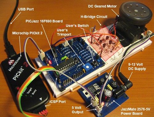
The following is the list of hardware and software used in this tutorial:
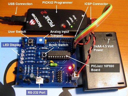
1. PICJazz 16F690 learning board from ermicro (the PICJazz 16F690 schema)
2. One 5 to 6 volt DC Motor (in this project I’am using geared DC Motor)
3. Four 2K2 Ohm ¼ watt resistor for the H-Bridge circuit
4. Four BC639 transistors (or equivalent) for the H-Bridge circuit
5. Four 1N4148 diodes for the H-Bridge circuit
6. One 100nF (0.1uF) 16 volt for the H-Bridge circuit
7. JazzMate 2576-5V power board, the 5 volt switching power supply from ermicro for the H-Bridge circuit.
8. Microchip MPLAB IDE v8.0 or higher
9. HITEC PICC-Lite PICC-Lite Version 9.60PL1
10. Microchip PICKit2 Programmer
In this tutorial first we will learn how to use the basic single output PWM mode and later on we will use the full bridge PWM mode for controlling the H-Bridge motor circuit.
1. The PIC16F690 Microcontroller PWM peripheral
The heart of PIC16F690 PWM lays on the TIMER2 peripheral, this timer is used as the basic counter generator used by the PWM peripheral to generating the PWM pulse, the following is the PIC 16F690 simplify PWM peripheral diagram (for complete explanation please refer to the datasheet):

The TMR2 counter register clock is supplied by the prescale circuit which can be selected using the T2CKPS1 and T2CKPS0 bits in the T2CON register, the TMR2 register value is compared to the PR2 register which determine the TOP value of TMR2 counter register. When the TMR2 value is equal to the PR2 value, then the TMR2 counter register will be reset to 0.

At the same time the value of TMR2 counter register is compared to the CCPR1L register value (actually with the CCPR1H register value, but since the CCPR1H equal to the CCPR1L than we could just say CCPR1L), when the TMR2 value equal to the CCPR1L register value than the PWM peripheral circuit will reset the CCP1 output (logical “0“) and when the TMR2 counter register equal to the PR2 register value than it will set the CCP1 output (logical “1“). Therefore the PR2 register determine the PWM period, by changing the PR2 value we could change the PWM period and this mean changing the PWM frequency as well. The PWM period could be calculated using this following formula:
PWM period = (PR2 + 1) x 4 x Tosc x (TMR2 prescale value) second
Where Tosc is the system clock period in second
PWM frequency = 1 / PWM Period Hz
While the PWM pulse width is depend on the CCPR1L register value, therefore by varying the CCPR1L register value, we could change the PWM pulse width. The PWM width can be calculated using this following formula:
PWM width = (CCPR1L:CCP1CON<5:4>) x Tosc x (TMR2 prescale value) second
This following table shows the PWM frequency and resolution with the 8 MHz clock:

The PWM output behavior is controlled by the CCP1CON, PWM1CON and PSTRCON registers, we will talk about these three registers shortly, but the important think to remember that all the TRIS (three states input/output) register for each of the PWM output ports: P1A, P1B, P1C and P1D should be set to the output mode.

2. Single Output Mode PWM
With single output PWM mode we could sent the same PWM signal to each of available PWM pins (i.e. P1A, P1B, P1C and P1D) or to all of them at the same time. Our first C program example will show you how this single output PWM mode works. Ok let’s pasting this following code into your Microchip MPLAB IDE:
// ***************************************************************************
//  File Name    : pwm.c
//  Version      : 1.0
//  Description  : Pulse Width Modulation (PWM)
//                 Single Output, Steering Mode
//  Author(s)    : RWB
//  Target(s)    : PICJazz 16F690 Board
//  Compiler     : HITECT PICC-Lite Version 9.60PL1
//  IDE          : Microchip MPLAB IDE v8.00
//  Programmer   : PICKit2
//  Last Updated : 03 Jan 2009
// ***************************************************************************
#include <pic.h>
/*   PIC Configuration Bit:
**   INTIO     - Using Internal RC No Clock
**   WDTDIS    - Wacthdog Timer Disable
**   PWRTEN    - Power Up Timer Enable
**   MCLREN    - Master Clear Enable
**   UNPROTECT - Code Un-Protect
**   UNPROTECT - Data EEPROM Read Un-Protect
**   BORDIS    - Borwn Out Detect Disable
**   IESODIS   - Internal External Switch Over Mode Disable
**   FCMDIS    - Monitor Clock Fail Safe Disable
*/
__CONFIG(INTIO & WDTDIS & PWRTEN & MCLREN & UNPROTECT \
  & UNPROTECT & BORDIS & IESODIS & FCMDIS);
// Using Internal Clock of 8 MHz
#define FOSC 8000000L
// Delay Function
#define	_delay_us(x) { unsigned char us; \
		       us = (x)/(12000000/FOSC)|1; \
		       while(--us != 0) continue; }
void _delay_ms(unsigned int ms)
{
  unsigned char i;
  if (ms == 0) return;
  do {
    i = 4;
    do {
      _delay_us(164);
    } while(--i);
  } while(--ms);
}
void main(void)
{
  unsigned int ipwm;
  unsigned char state;
OSCCON=0x70; // Select 8 MHz internal clock
  TRISC = 0x00;        // Set All on PORTC as Output
  ANSEL = 0x00;        // Set PORT AN0 to AN7 digital I/O
  ANSELH = 0x00;       // Set PORT AN8 to AN11 as Digital I/O
  PORTC = 0x00;        // Turn Off all PORTC
  /* Init PWM for Single Output */
  CCP1CON=0b00001100;  // Single PWM mode; P1A, P1C active-high; P1B, P1D active-high
  CCPR1L=0;            // Start with zero Duty Cycle
  T2CON=0b00000101;    // Postscale: 1:1, Timer2=On, Prescale = 1:4
  PR2=0x65;            // Frequency: 4.90 kHz
  TMR2=0;              // Start with zero Counter

  PSTRCON=0b00000100;  // Enable Pulse Steering on P1C (RC3)
  state=0;             // Start with state 1
  for(;;) {
    ipwm=0;
    while (ipwm < 255) {
      CCPR1L=++ipwm;
      _delay_ms(5);     // Delay 5 millisecond
    }

    ipwm=0xff;
    while (ipwm > 0) {
      CCPR1L=--ipwm;
      _delay_ms(5);     // Delay 5 millisecond
    }

     _delay_ms(100);    // Delay 100 millisecond
    if (state == 0) {
      state=1;
      PSTRCON=0b00001000;  // Enable Pulse Steering on P1D (RC2)
    } else if (state == 1) {
      state=2;
      PSTRCON=0b00001100;  // Enable Pulse Steering on P1C and P1D (RC3 and RC2)
    } else {
      state=0;
      PSTRCON=0b00000100;  // Enable Pulse Steering on P1C (RC3)
    }
  }
}
/* EOF: pwm.c */
This C program basically will use only P1C and P1D PWM output ports, since these ports are attached to the LEDs on the PICJazz 16F690 board. The program will use the PWM pulse steering mode to make these two LEDs to slowly turn to bright and slowly turn to dark by changing the PWM duty cycle.
2.1. CCP1CON: Enhance CCP1 Control Register
This register is use to select the PWM output configuration bit and PWM mode.

By setting P1M1=0 and P1M0=0 bits in the CCP1CON register we select the single output PWM; setting the CCP1M3=1, CCP1M2=1, CCP1M1=0 and CCP1M0=0 in the CCP1CON register we select the PWM mode with P1A, P1C active-high; P1B, P1D active-high as this following code:
/* Init PWM for Single Output */
CCP1CON=0b00001100;  // Single PWM mode; P1A, P1C active-high; P1B, P1D active-high
CCPR1L=0;            // Start with zero Duty Cycle
In this tutorial we just set the additional 2 LSB extended bits (DC1B1 and DC1B0) to all zero (logical “0“) for the CCPR1L register (10-bit wide). We start by setting the CCPR1L to zero mean we start with zero duty cycle (no PWM output). The next step is to configure the TIMER2 control register:

This register is used to set the postscale, activate the TIMER2 peripheral and set the prescale clock used by the TMR2 counter register. BY setting the T2CKPS1=0 and T2CKPS0=1 in the T2CON register we select the 1:4 prescale; and by setting the TMR2ON to logical “1” we activate the TIMER2 peripheral.
T2CON=0b00000101;    // Postscale: 1:1, Timer2=On, Prescale = 1:4
PR2=0x65;            // Frequency: 4.90 kHz
TMR2=0;              // Start with zero Counter
On the PWM mode, we are not using the postscaller output therefore we just set all the postscale bits (TOUTPS3, TOUTPS2, TOUTPS1 and TOUTPS0) to all zero. Setting the PR2=0x65 (or 101 decimal) with the 1:4 prescale and system clock of 8 MHz, then we could calculate the PWM output frequency according to the formula above as follow:
PWM period = (PR2 + 1) x 4 x Tosc x (TMR2 prescale value) second
PWM period = (101 + 1) x 4 x (1 / 8000000) x 4 = 0.000204 second
PWM frequency = 1 / PWM period = 1 / 0.000204 = 4901.96 Hz = 4.90 kHz
2.2. PSTRCON: Pulse Steering Control Register
In the single output PWM mode this register is use to control where the PWM ports to be used as the PWM output signal.

By activating the desire steering bit in the PSTRCON register, we could control the PWM output signal whether to use just one port or simultaneously use all the available PWM output ports. On the example program above we use the program state to change these bits. First we activate only the P1C (RC3) port:
PSTRCON=0b00000100;  // Enable Pulse Steering on P1C (RC3)
state=0;             // Start with state 1
Then inside the endless loop we change these bits according to the state status as this following code:
if (state == 0) {
  state=1;
  PSTRCON=0b00001000;  // Enable Pulse Steering on P1D (RC2)
} else if (state == 1) {
  state=2;
  PSTRCON=0b00001100;  // Enable Pulse Steering on P1C and P1D (RC3 and RC2)
} else {
  state=0;
  PSTRCON=0b00000100;  // Enable Pulse Steering on P1C (RC3)
}
The steering sync bit (STRSYNC) in the PSTRCON register is set to zero, means the output steering update occur at the beginning of the instruction cycle.
2.3. Inside the C Program
The C program begins by selecting the 8 MHz internal clock and setting all the I/O ports used on this examples. After doing the PWM and TIMER2 peripherals setup, we go the endless loop (the for(;;) C statement with no argument); inside this loop we use the CCPR1L register to change the PWM duty cycle by assigning the value from 0 to 255 for turning the LEDs slowly from dark to bright and assigning the CCPR1L register value from 255 to 0 for turning the LEDs from bright to dark.
ipwm=0;
while (ipwm < 255) {
  CCPR1L=++ipwm;
  _delay_ms(5);     // Delay 5 millisecond
}

ipwm=0xff;
while (ipwm > 0) {
  CCPR1L=--ipwm;
  _delay_ms(5);     // Delay 5 millisecond
}
2.4. Downloading the Code
After compiling and simulating your code hook up your PICKit2 programmer to the PICJazz 16F690 board ICSP port turn the PICJazz 16F690 power. From the MPLAB IDE menu select Programmer -> Select Programmer -> Pickit2 it will automatically configure the connection and display it on the PICkit2 tab Output windows:


Now you are ready to down load the code from MPLAB IDE menu select Programmer -> Program; this will down load the HEX code into the PICJazz 16F690 board:
3. Full Bridge Mode PWM
After learning the PWM principal by using the single output mode, now we come to the best part; the ability to easily control the H-Bridge DC motor circuit is what makes the PIC microcontrollers unique among the other microcontroller’s types. Ok let’s take a look at the following C program code:
// ***************************************************************************
//  File Name    : pwm2.c
//  Version      : 1.0
//  Description  : Pulse Width Modulation (PWM)
//                 H-Bridge DC Motor Controller
//  Author(s)    : RWB
//  Target(s)    : PICJazz 16F690 Board
//  Compiler     : HITECT PICC-Lite Version 9.60PL1
//  IDE          : Microchip MPLAB IDE v8.00
//  Programmer   : PICKit2
//  Last Updated : 03 Jan 2009
// ***************************************************************************
#include <pic.h>
/*   PIC Configuration Bit:
**   INTIO     - Using Internal RC No Clock
**   WDTDIS    - Wacthdog Timer Disable
**   PWRTEN    - Power Up Timer Enable
**   MCLREN    - Master Clear Enable
**   UNPROTECT - Code Un-Protect
**   UNPROTECT - Data EEPROM Read Un-Protect
**   BORDIS    - Borwn Out Detect Disable
**   IESODIS   - Internal External Switch Over Mode Disable
**   FCMDIS    - Monitor Clock Fail Safe Disable
*/
__CONFIG(INTIO & WDTDIS & PWRTEN & MCLREN & UNPROTECT \
  & UNPROTECT & BORDIS & IESODIS & FCMDIS);
// Using Internal Clock of 8 MHz
#define FOSC 8000000L
// Delay Function
#define	_delay_us(x) { unsigned char us; \
		       us = (x)/(12000000/FOSC)|1; \
		       while(--us != 0) continue; }
void _delay_ms(unsigned int ms)
{
  unsigned char i;

  if (ms == 0) return;
  do {
    i = 4;
    do {
      _delay_us(164);
    } while(--i);
  } while(--ms);
}
void main(void)
{
  unsigned int ipwm;
  unsigned char direction;
OSCCON=0x70; // Select 8 Mhz internal clock
  TRISC = 0x00;        // Set All on PORTC as Output
  TRISA = 0x03;        // Input for RA0 and RA1
  ANSEL = 0x01;        // Set PORT AN0 to analog input AN1 to AN7 digital I/O
  ANSELH = 0x00;       // Set PORT AN8 to AN11 as Digital I/O
  PORTC = 0x00;        // Turn Off all PORTC
  /* Init PWM for Full Bridge Output */
  CCP1CON=0b01001100;  // Full Bridge Forward; P1A, P1C active-high; P1B, P1D active-high
  CCPR1L=0;            // Start with zero Duty Cycle
  T2CON=0b00000101;    // Postscale: 1:1, Timer2=On, Prescale = 1:4
  PR2=0x65;            // Frequency: 4.90 KHz
  TMR2=0;              // Start with zero Counter
  /* Init ADC */
  ADCON0=0b00000000;   // Select Left justify result. ADC port channel 0
  ADCON1=0b00110000;   // Select the FRC for 8 MHz
  ADON=1;	        // turn on the ADC conversion module
  direction=0;         // Start with Forward Direction
  ipwm=0;
  for(;;) {
    if (RA1 == 0) {           // Change the Motor Direction when pressed
     _delay_ms(1);
     if (RA1 == 0) {          // Read again for simple debounce
       if (direction == 0) {
         direction=1;         // Reverse direction
         P1M1=1;
         P1M0=1;
       } else {
         direction=0;         // Forward direction
         P1M1=0;
         P1M0=1;
       }
     }
    }
    GODONE=1;	              // initiate conversion on the channel 0
    while(GODONE) continue;  // Wait conversion done

    ipwm = ADRESH;           // Get the highest 8 bit MSB result, ignore the 2 bit LSB
    CCPR1L=ipwm;             // Set the Duty Cycle base on the ADC result
    /* Blink the LED attached on RC0 */
    RC0=1;                   // Turn On
    _delay_ms(ipwm);
    RC0=0;                   // Turn Off
    _delay_ms(ipwm);
  }
}
/* EOF: pwm2.c */
The basic PWM setup routines is almost the same with our previous program, but in this program I used the PIC 16F690 ADC peripheral for adjusting the DC motor speed; the motor speed is depend on the voltage value read by the PIC 16F690 ADC peripheral from the PICJazz 16F690 board user’s trimpot that works as the voltage divider circuit. This value will be assigned to the CCPR1L duty cycle register.
I also use the PICJazz 16F690 user’s switch that works as a toggle switch to change the DC motor direction; and to make it more interesting, I use the LED attached to the RC0 port as the program life beacon; this LED will blink according to the value we assigned to the CCPR1L register.
3.1. Full Bridge PWM Mode Setup
The full bridge PWM mode is selected by setting the P1M1 and P1M0 bits in the CCP1CON register, there are 2 available modes for the full bridge PWM mode; the first one is called full bridge output forward, this can be selected by setting the P1M1=0 and P1M0 = 1 in the CCP1CON register. In this mode the P1D pin will be the modulated port; P1A port will active; while P1B, P1C will inactive:


On the forward full bridge PWM mode the TR1 transistor will on saturate and the TR4 transistor will on/off base on the PWM signal supplied by P1D port, while the TR2 and TR3 transistors inactive. The current will flow from TR1 transistor through DC Motor and go to the TR4 transistor, this make the DC motor to turn on the forward direction.
The second full bridge PWM mode is the reverse full bridge PWM mode, this mode can be selected by setting the P1M1=1 and P1M0 = 1 in the CCP1CON register. In this mode the P1B pin will be the modulated port; P1C port will active; while P1A, P1D will inactive:


On the reverse full bridge PWM mode the TR3 transistor will on saturate and the TR2 transistor will on/off base on the PWM signal supplied by P1B port, while the TR1 and TR4 transistors inactive. The current will flow from TR3 transistor through DC Motor and go to the TR2 transistor, this make the DC motor to turn on the reverse direction.
The following is the C program code for the PWM setup we use in this project:
/* Init PWM for Full Bridge Output */
CCP1CON=0b01001100;  // Full Bridge Forward; P1A, P1C active-high; P1B, P1D active-high
CCPR1L=0;            // Start with zero Duty Cycle
T2CON=0b00000101;    // Postscale: 1:1, Timer2=On, Prescale = 1:4
PR2=0x65;            // Frequency: 4.90 KHz
TMR2=0;              // Start with zero Counter
The other register that I mention before is the PWM1CON register (enhanced PWM control register). This register is used in half bridge PWM mode to put a time delay to the actual PWM signal transition from zero to active; we are not using this feature on the full bridge PWM mode.
3.2. The PIC 16F690 ADC Peripheral Setup
The ADC peripheral is used to read the voltage value on the analog input port RA0, this voltage value is supplied by the user’s trimpot on the PICJazz 16F690 board. Adjusting the trimpot means changing the voltage value as well; by converting this voltage value to the digital equivalent value and assign this value to the CCPR1L (duty cycle) register, we could change the PWM duty cycle and this will effecting the DC motor speed.
The complete PIC microcontroller ADC setup explanation could be read on the article “PIC Analog to Digital Converter C Programming” posted on this blog. The following is the C program code for setting the PIC 16F690 ADC peripheral:
/* Init ADC */
ADCON0=0b00000000;   // Select Left justify result. ADC port channel 0
ADCON1=0b00110000;   // Select the FRC for 8 MHz
ADON=1;	             // Turn on the ADC conversion module
By setting the ADFM bit to logical “0” in the ADCON0 register we use the “left justified” result. This mean the higher 8 bits ADC result value will be placed in the ADRESH register and the lower 2 bits ADC result value in the ADRESL register, because we just need the 8 bit value for the CCPR1L register, so the lowest 2 bits value in ADRESL register can be ignored:
ipwm = ADRESH;           // Get the highest 8 bit MSB result, ignore the 2 bit LSB
CCPR1L=ipwm;             // Set the Duty Cycle base on the ADC result
3.3. Inside the C Program
The C program begins by selecting the 8 MHz internal clock and setting all the I/O ports used on this examples. After doing the PWM, TIMER2 and ADC peripherals setup, we go the endless loop (the for(;;) C statement with no argument); inside this loop first we read the user’s switch, this switch is attached to the input port RA1 and work as the toggle switch to change the DC motor direction:
if (RA1 == 0) {            // Change the Motor Direction when pressed
  _delay_ms(1);
  if (RA1 == 0) {          // Read again for simple debounce
    if (direction == 0) {
      direction=1;         // Reverse direction
      P1M1=1;
      P1M0=1;
    } else {
      direction=0;         // Forward direction
      P1M1=0;
      P1M0=1;
    }
  }
}
By setting the P1M1=1 and P1M0=1 bits in the CCP1CON register, we select the reverse full bridge PWM mode; setting the P1M1=0 and P1M0=1 bits in the CCP1CON register, we select the forward full bridge PWM mode.
The PIC ADC peripheral than read the analog input channel 0 (RA0) port and assigned the value to the CCPR1L register and as the _delay_ms() function argument to the life beacon LED attached to the output port RC0.
GODONE=1;	         // initiate conversion on the channel 0
while(GODONE) continue;  // Wait conversion done

ipwm = ADRESH;           // Get the highest 8 bit MSB result, ignore the 2 bit LSB
CCPR1L=ipwm;             // Set the Duty Cycle base on the ADC result
/* Blink the LED attached on RC0 */
RC0=1;                   // Turn On
_delay_ms(ipwm);
RC0=0;                   // Turn Off
_delay_ms(ipwm);
3.4. Downloading the Code
After compiling and simulating your code hook up your PICKit2 programmer to the PICJazz 16F690 board ICSP port turn the PICJazz 16F690 power. From the MPLAB IDE menu select Programmer -> Select Programmer -> Pickit2 it will automatically configure the connection and display it on the PICkit2 tab Output windows:


Now you are ready to down load the code from MPLAB IDE menu select Programmer -> Program; this will down load the HEX code into the PICJazz 16F690 board:
After all the hard work, now it’s time to watch to your PIC microcontroller controlling the H-Bridge DC motor circuit:
Bookmarks and Share


Related Posts
105 Responses to “H-Bridge Microchip PIC Microcontroller PWM Motor Controller”
Comment by pichaha.
Hi rwb,
I would like to ask if there is any motor driver or motor driver circuit that can receive analogue +-12V input voltage and produce relevant output voltage (with current amplified). Please advice, thank you very much.
Regards
Comment by rwb.
Yes is possible, basically the circuit has to shift the input voltage to the positive level and trim it to 0-5 volt variation so it can be processed by the microcontroller.
Comment by pichaha.
Hi, thanks for the reply.
I am sorry I forget to mention the target processor I am using is not a microcontroller, it is a microbox which can receive and produce voltage of up to 12V. So, I just want to know if there is any motor driver or motor driver circuit which can handle this voltage range (because if I am not wrong, the L293D can only sustain voltage variation of not more than 5V, right?) Please advice, thank you very much.
Regards
Comment by rwb.
The L293D maximum logic level input (Vi) and enable (Ve) voltage is 7 volt, the logic supply voltage is 36 volt, and the motor supply voltage is 36 volt, therefore you just need to use the voltage divider circuit to trim the microbox output (i.e. 12 volt) down bellow 7 volt.
Comment by pichaha.
Hi thanks for the reply.
What is the logic supply voltage for, is it the supply voltage for the chip? Previously, I use this motor driver to access digital input and output via microcontroller. But this time I am using it for analogue input and output. What is the changes that I should make. The output of the microbox should go to enable pin or input pin?? Thank you very much.
Regards
Comment by rwb.
Yes, the Vss pin is used to supply the motor controller logic inside the chip and the Vs pin is used for supply the motor. All the logical input is not an analog, they are all digital. Usually the enable pins (i.e. ENABLE1 and ENABLE2) are used to control the motor speed by supplying the PWM signal on it and the other logical pins (i.e. IN1,IN2,IN3, and IN4) are used to control the motor direction. If the analog is used to control the motor speed, then you have to convert the analog signal to the PWM signal in order to used it with L293D.
Comment by pichaha.
Hi, thanks for the reply.
I have a doubt. If the microbox I am using can only produce one anologue output to control one DC motor, how am I going to control the rotating direction of the motor using normal motor driver chips? What is the difference between supplying a +12V signal and -12V signal to the motor. Will the motor direction be reversed via this way without inverting the terminal connection of the motor?
I am asking this because the microbox I am using will be working with the matlab simulink in PC and the project I am doing is a closed loop control system. In the closed loop control, if the set point is less than the process variable, the manipulated signal will become negative, so as to the output signal.
Please advice. Your assistance is much appreciated. Thank you very much.
Regards
Comment by rwb.
If you plan to use +12V and -12V supply then you could try to use the half bridge DC motor driver circuit.
Comment by pichaha.
Hi thanks for the reply.
I am sorry, I have made a mistake here. The maximum analogue voltage that can be generated from the microbox is +-10V instead of 12V, so as to the maximum analogue input voltage that can be sustained by the microbox.
Apart from this, can I know what is the difference between supplying +10V and -10V voltage to the DC motor without inverting its terminal. Thank you very much. (For the half bridge circuit that you have suggested, I will try to study later.)
Regards
Comment by rwb.
You need to study the half bridge circuit! Basically this circuit required a symmetric power supply (i.e. +V, GND, and -V) in order to change the DC motor direction (i.e. forward and reverse).
Comment by chandra.
Hi….I am again here asking some doughts…..
The circuit and the program is working well…
This program at stat up if we make to use state machine algorithm; on the first power up the state is 0 and the DC motor is Off. any change in the RA1 input condition (RA1=0 or RA1=1) will change the state to 1, which mean the DC motor is On.
At running I want Stop possition….
How can it Possible?
So I want use RA1===0 for forwd…
and Ra2== 0 for revese….
and both at ===1 is stop…
Can u tell the code modifications…..
Thanks..
Comment by chandra.
Now writing clearly….
RA1 == 0 and RA2 == 1 is forwd..
RA1 == 1 and RA2 == 0 is reverse….
RA1 == 1 and RA2 == 1 is stop.
RA1 == 0 and RA2 == 0 is stop.
Can u say the code modicications….
Thanks..
Comment by rwb.
You just need to use a simple if condition in order to achieve what you need. Here the pseudo code:
SW_RA1 = read_RA1()
SW_RA2 = read_RA2()
if (SW_RA1 <> SW_RA2) then
if (SW_RA1 = 0 AND SW_RA2 = 1) then
direction=forward
end
if (SW_RA1 = 1 AND SW_RA2 = 0) then
direction=reverse
end
else
direction=stop
end
motor_move(direction)
Comment by chandra.
Hi….I tried the code at MPLAB it giving many error messages….Can u Provide the full code……
Thanks…..
Comment by rwb.
All the codes provides in this blog has been tested, make sure you install the Microchip MPLAB IDE and Microchip HITECH C Compiler correctly
Comment by chandra.
Hi….I tested that code is working…..But…
As per your advice,I try to edit and compile the code This….
SW_RA1 = read_RA1()
SW_RA2 = read_RA2()
if (SW_RA1 SW_RA2) then
if (SW_RA1 = 0 AND SW_RA2 = 1) then
direction=forward
end
if (SW_RA1 = 1 AND SW_RA2 = 0) then
direction=reverse
end
else
direction=stop
end
motor_move(direction)
When I am trying this…Giving error message..So can u edit and post the full code for this function.
Thanks…
Comment by rwb.
The code is called “pseudo code”, which mean its only show you the program logic not a real C code. You have to make your own code when you want to modify this project C code.
Comment by chandra.
Hi…Thanks for your kind reply……
I define as follow…
#define forward;
P1M1=0;
P1M0=1;
#define reverse;
P1M1=1;
P1M0=1;
How can I define the stop……
I need the stop mode….
Thanks…
Comment by rwb.
You could simply assign the duty cycle on CCPR1L register to 0 to stop the motor.
Comment by chandra.
I am confusing this stage.Really…. when the control at level of full speed…. when change the switch to Stop possition…I need stop….
Please explain abt stop ..
How han I define…
#define forward;
P1M1=0;
P1M0=1;
#define reverse;
P1M1=1;
P1M0=1;
Write about me stop….
Thanks…
Comment by olam.
I have this project working ok. But when I pressed the button it changed the direction only once, and never return, also when ajust the pot it’s freeze the LED and stuck there.
Could you point out the error I have made? I use PCkit3 programmer, A Low pin count demo-board
From Microchip. Where or how could I purchase your Demo and learning board?
Thank you
Comment by rwb.
Check your program and circuit again. The AVRJazz 20PIN demo board could be purchased from http://www.ermicro.com
Comment by olam.
Hello! Mr. Besinga.
Thank you so much to reply my questions.
I got this worked ok now.
Merry Christmas and Happy New year
To you and your family !!!
Comment by aredhel_vlsi.
Hello man, thank you very much for this tutorial !!
It’s usefull to advise some code while studying. I’m a beginner and I use the power control module. Have you done anything with this ,or only with CCP?
Thanx again
Comment by rwb.
What did you mean by using the “power control module” on Microchip PIC16F690 Microcontroller?
Comment by aredhel_vlsi.
Excuse me, there is a power control module at PIC 18F4331… I didn’t notice that you use PIC16F.. But your logic helped me a lot. So I guess you haven’t ever used 18F family?
Comment by Izanur.
Hi, Thanks to you for your great-tutorial !!
Using this 16F690 I want to take three analog value using RA0,RA1,RA2. Now, if RA0>RA1 the voltage will gradually increase from 60-80%. Again if RA0=RA0,RA1 or RA2<=RA0,RA1 the voltage will be 50%.
What will be the program? This will works as charger. Please help me….. I am Newer..
Comment by Izanur.
Analog value will be taken as input.By PWM the percentage will vary. Which i did not mentioned in the previous..
Thanks
Comment by Izanur.
Pls. give the Answer
Comment by rwb.
You could use the C language if condition to change the PWM duty cycle (CCPR1L register) value based on the RA0, RA1, and RA2 analog input. This article show you how to read multiple analog input on PIC16F690 and how to use the analog value to control a servo Basic Servo Motor Controlling with Microchip PIC Microcontroller.
Comment by Izanur.
I want to take voltage(6v) & current(10mA) value as analog input, according to this analog value I want to change the PWM duty cycle. Please help me, how can i do it….?????
thanks.. Please know me….
Comment by rwb.
The PIC16F690 microcontroller analog input only could handle voltage level start from 0 to 5 volt. Therefore for 6 volt voltage level you need to use the voltage divider circuit and for the current you need to use a current to voltage transducer such as LEM FHS 40-P/SP600. Next based on the ADC reading on both these voltage inputs, you could adjust the PWM duty cycle using the CCPR1L register.
Comment by Izanur.
Hi, i want to do it using timer 2. But i am not clear, what will be the C programme code of the project. Actually i want to make a charger, after taking analog input it will creates different PWM based on the analog input value. say if AN0 value>3 & AN1 value<6, then any pin of C-port will create 3V
pwm signal again if AN0 value6 then same pin of C-port will create 8V pwm.
Some of code given below….
Please complete the code according to my requirement above.
I am new in programming.
Thanks, You are Great….
[Code Truncated…]
Comment by Izanur.
Please, Give me the answer…..
Comment by rwb.
You need to read more about the PWM principle on the Microchip PIC16F690 microcontroller in order to understand how it really work. Remember the PIC16F690 PWM output port will not create 3 volt nor the 8 volt output but it will create a pulse signal from 0 to 5 volt with a duty cycle (HIGH vs LOW) vary from 0 to 100%.
Comment by GeorgeAE.
It is anyway you can provide me the C code, so i can take a look . Thank you.
Comment by rwb.
You could read the article above for the complete C code for this project.
Comment by Jolly.
Hi Mr.rwb
Thanks you so very much for your tutorials. I got a lot of knowledge from your blog. Excume me, can you tell me, how to know 2 dc motors position in rectangular coordinates and pls guide me which articles and books I should read. Thank you.
Comment by Izanur.
What is difference between PORTC & TRISC. To show output, have i need to set both(PORTC & TRISC) to Zero(0) or Please tell me details about PORTC & TRISC.
Thank You.
Comment by rwb.
Because the PORTC is the bidirectional port (i.e. Input and Output), therefore we need to configure it whether to use it as input or output port. To configure PORTC as the input port you need to set the TRISC (Port C Tri-State) register to 0xFF, while assigning the value of 0x00 to the TRISC register will configure the PORTC as the output port.
Comment by harish.
Hi i am trying to build Dual Dc Motor Speed control using PIC Controller. I have to use an analog joystick to control the speed and direction. Its going to be used on wheel chairs for disabled. Can you plaese provide me with any information .thank you
Comment by rwb.
Basically the joystick has two potentiometers. These two potentiometers will be used two analog ports in PIC microcontroller and use the ADC peripheral to read the analog value. Next use these values to control motor speed (PWM) and direction.
Comment by harish.
thanks a lot for the reply. I have 2 more questions.
1. I am going to use an arduino (atmega328) controller and i have to make sure that i program it and put it on my board is it possible?? i dont want to have 2 seperate boards.
2. Also is it possible for you to provide me with a circuit diagram please??
Comment by rwb.
Yes you could use arduino board to control the motor (you need a motor driver circuit) and you could use the arduino board analog input to read the potentiometer to control both speed and direction. For the circuit first you need to find a suitable motor driver (arduino motor shield if possible) for your needs, next use two analog (e.g. A0 and A1) input on the arduino board and connect it to the potentiometer (there are a plenty example in the arduino playground website)
Comment by harish.
Hi, I wanted to know if there are any H BRIDGE with 20A as mine is a 300W and 24V DC MOTOR??
Comment by rwb.
For this particular need you have to build your own H-Bridge motor driver, try to look at the Open Source Motor Control (OSMC) project
Comment by sam781.
Very good tutorial indeed. I need a little more info regarding single output mode. In the single output mode, all the output pins (P1A, P1B, P1C & P1D) will have the same waveform. I need output like – for the first cycle only A and C will be enabled and in the next cycle only B and C will be enabled. This is for full bridge converter.
Comment by rwb.
In single output mode, you could use the PSTRCON register to control the P1A, P1B, P1C, and P1D output by enabling the corresponding STRA, STRB, STRC, and STRD bits.
Comment by wall e.
I already have a pic 16F877A micro chip can I use it for this
Comment by wall e.
please can you provide easy and medium cost project like the 1st project you provide to make line following robot by transistor basis,but it should be more accurate than transistor base one.
I have poor knowledge in pic’s and programming so I’m mostly appreciate projects without pics
Comment by rwb.
Yes you could but you need to modify the C program. For the robotics project you could try the “The LM324 Quad Op-Amp Line Follower Robot with Pulse Width Modulation” project.

Comment by rwb.
Yes, just use state machine algorithm; on the first power up the state is 0 and the DC motor is Off. any change in the RA1 input condition (RA1=0 or RA1=1) will change the state to 1, which mean the DC motor is On.