Blog Entry
Behavior Based Artificial Intelligent Mobile Robot with Sharp GP2D120 Distance Measuring Sensor – BRAM Part 2
June 8, 2009 by rwb, under Robotics.
What is the intelligent anyway; could we categories how the bees building their tiny hexagonal compound nest, ants searching for their food or birds migration using precision navigation over continental are the intelligent acts; or we as the human being with our cultures and civilizations is the only one that can be categories as the intelligent being? These kinds of question probably will not have satisfied answer as the answer is more philosophy terms rather than physics or mathematics law; therefore I think anyone could give their own opinion to this question.
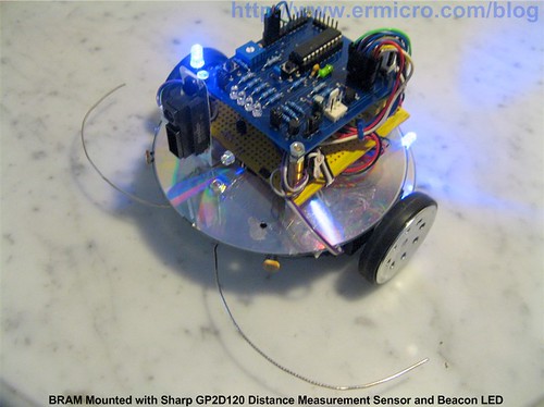
Continuing our tutorial about BRAM (Building BRAM your first Autonomous Mobile Robot using Microchip PIC Microcontroller – Part 1); this time we will learn how to program BRAM brain and at the same time we learn how to use the Microchip PIC16F690 microcontroller EUSART (Enhanced Universal Synchronous Asynchronous Receiver Transmitter) peripheral for debugging BRAM program; later on we will add the distance measuring sensor for enhancing the obstacle avoidance capabilities to BRAM; this time we will use sharp GP2D120 analog distance measuring sensor.
As you learn through these two tutorials, building BRAM is not just a matter of building a robot; which of course is cool (…yeah…I’ve build a robot) but is more than that; building a robot required you to use your imagination and knowledge about how to build the robot chassis, choosing the right stuff to put on your robot, maximizing the microcontroller’s peripherals to support your robot and finally programming your robot; this kind of knowledge is very important in the embedded system control used in many industries.
BRAM Steering
BRAM steering method use what is called “differential drive“, this method use two DC motor mounted in fixed positions on the left and right side of BRAM chassis; each motor can rotate independently both in forward or reverse direction. By controlling these two DC motors rotate direction; we could control how BRAM move.

The BRAM DC motor is connected to the popular dual channel H-Bridge SGS-Thompson L293D chip; by feeding the right logic to the 4 buffers inputs we could get the desired result:

One of the important things is the DC motor polarity because the polarity will effect the DC motor rotate direction, you should experiment with it or you could simply change the logic truth table shown above to reflect your DC motor condition. For example in order to make your left DC motor to rotate counterclockwise than the L293D INPUT1 should be logical “1” and the INPUT2 should be logical “0” while the enable input for the buffer (ENABLE 1 and ENABLE 2) should be remain high (logical “1“) and vise versa.
The C function that control the BRAM steering is BRAM_steer(), which simply supply the right logic to the L293D input ports according to the truth table shown above:
// Define BRAM Steering
#define MOVE_FORWARD 0
#define TURN_LEFT 1
#define TURN_RIGHT 2
#define ROTATE_LEFT 3
#define ROTATE_RIGHT 4
#define MOVE_BACKWARD 5
#define FULL_STOP 6
...
...
void BRAM_steer(unsigned char steer)
{
  switch(steer) {
    case MOVE_FORWARD:
      RC4=0; RC5=1;  // Right Motor On Forward
      RC6=1; RC7=0;  // Left Motor On Forward
      break;
    case TURN_LEFT:
      RC4=0; RC5=1;  // Right Motor On Forward
      RC6=0; RC7=0;  // Left Motor Off
      break;
    case TURN_RIGHT:
      RC4=0; RC5=0;  // Right Motor Off
      RC6=1; RC7=0;  // Left Motor On Forward
      break;
    case ROTATE_LEFT:
      RC4=0; RC5=1;  // Right Motor On Forward
      RC6=0; RC7=1;  // Left Motor On Reverse
      break;
    case ROTATE_RIGHT:
      RC4=1; RC5=0;  // Right Motor On Reverse
      RC6=1; RC7=0;  // Left Motor On Forward
      break;
    case MOVE_BACKWARD:
      RC4=1; RC5=0;  // Right Motor On Reverse
      RC6=0; RC7=1;  // Left Motor On Reverse
      break;
    case FULL_STOP:
      RC4=0; RC5=0;  // Right Motor Off
      RC6=0; RC7=0;  // Left Motor Off
      break;
  }
}
BRAM Speed Control
BRAM speed is controlled by PIC16F690 microcontroller PWM (Pulse Width Modulation) peripheral; by supplying this PWM pulse to the L293D enable input port, we could adjust the DC motor speed from 0% to 100% full speed. Using the Pulse Steering Mode and select the PWM output to the RC3 ports we cold simply change the pulse width by changing the PIC16F690 microcontroller CCPR1L register value from 0 to 255 using the BRAM_speed() function bellow:
// BRAM Speed and Steering Functions
void BRAM_speed(unsigned char sp)
{
  // Adjust the PWM CCPR1L register
  CCPR1L=sp;
}
BRAM default speed is controlled by the value taken from RA0 which configured as ADC (Analog to Digital) input port connected to the 10K user’s trimport on the PICJazz 16F690 board; therefore by adjusting the voltage level input to the RA0 port through 10K trimport and passing the ADC value to BRAM_speed() function we could easily adjust BRAM DC motor speed. Below is the C code for initialized the PIC16F690 single PWM output with pulse steering mode, for more information about using the PIC16F690 PWM please refer to my previous posted blog H-Bridge Microchip PIC Microcontroller PWM Motor Controller:
/* Init PWM for Single Output */
CCP1CON=0b00001100;  // Single PWM mode; P1A, P1C active-low; P1B, P1D active-low
CCPR1L=0;            // Start with zero Duty Cycle
PSTRCON=0b00000100;  // Enable PIC Pulse Steering PWM on RC3 Port
T2CON=0b00000101;    // Postscaler: 1:1, Timer2=On, Prescaller = 1:4
PR2=0x65;            // Frequency: 4.90 KHz
TMR2=0;              // Start with zero Counter
The current implementation of the BRAM program just use the default speed read from the 10K trimport, but you could easily overwrite the speed by calling the BRAM_speed() function.
BRAM Obstacle and Light Sensor
Both obstacle and light sensor utilized the PIC16F690 microcontroller ADC peripheral; the BRAM obstacle sensor just using the two basic mechanics switches to detect the obstacle. These switches arms is extended by using the modified paper clip so its look like animal whisker (which actually used by many animals to sense its surrounding). Normally for mobile robot this bump switch is use as the last defense again the obstacles detection, most modern mobile robot also equipped with proximately sensors to sense the obstacle far before the robot bump to the object; later on this tutorial we will put this sophisticated sensor on BRAM.
BRAM light sensor use two LDR (Light Dependent Resistor) to locate light, base on the differences light intensity level receipt by these two LDR we could easily navigate BRAM DC motor toward the light source.

To maximize the LDR sensors; you have to put the LDR approximately facing about 45 degree from the robot’s center. Using a simple bang-bang close loop control with the hysteresis, BRAM could navigate smoothly toward the light source; for more information about using bang-bang close loop control please refer to my previous posted blog Basic Servo Motor Controlling with Microchip PIC Microcontroller.
BRAM Brain
Now come to the most interesting part, as we will give BRAM an artificial life, so it behave like moth that interest is light (photovore) but if the light is to bright than it run from it (light avoidance) and when the light intensity is not bright enough than BRAM will start to explore the room searching for light and use its whisker to avoid the obstacle.
The classical approach to the artificial intelligent is to use world modeling inside the computer, plans the action and execute these plans; this kind of method only suitable for strictly controlled environment such as robot’s arm manipulator used in the car line assembly industry. For autonomous mobile robot the world modeling is become very complex and almost impossible to put all the unpredictable and dynamically change environment inside this model; for example your cat suddenly chasing your robot, how we could plan to avoid such an action or your robot suddenly bump to the bone that your dogs just bring it from outside.
Until the late 1980 this classical method still the dominant approach to the autonomous mobile robot; with complex mathematical equation to model the world, the mobile robot become unreliable because it’s reaction to the environment will be very slow, besides using this method, for sure you will not be able to run it on the 8-bits class microcontroller with only have 4K words RAM like Microchip PIC16F690 microcontroller.
The solution for this situation is to use bottom up approach (on the contrary of top down approach used in classic artificial intelligent), this method is usually called behavior based artificial intelligent. First introduced in 1986 by Rodney A. Brooks with his subsumption architecture; his theory suggest that first we write the robot’s basic primitive behavior program such as obstacle avoidance and add more advance behavior on top of it; for example light avoidance, light follower, exploring, etc. Each of these behaviors is given a fixed priority to take control of the robot’s actuators; the most important behavior will be given a higher priority such as the obstacle avoidance behavior. The combination of all these behaviors will produce the desired response to the robot’s environment.

As shown by the diagram above; BRAM has four basic behaviors and each of these behaviors is given a fixed priority start from the higher (obstacle avoidance: 1) to the lowest (exploring: 4). The priority selector is the algorithm method which guarantees that only one behavior could take control to the BRAM motor at a time; this priority selector work as a switch that connects the behavior action directly to the BRAM motor control. For example if the light follower detect the light at the same time the whisker bump to the obstacle, then the priority selector will ensure that the obstacle avoidance should be served first because it has a higher priority over the light follower behavior.
For the purpose of this tutorial and to keep the program simple, BRAM implement the priority selector using just a fixed sequence call to these behavior functions, later on the BRAM final program we will fully implement this algorithm.
/* Start Read All the ADC input here */
...

// BRAM Steering Speed
BRAM_speed(speed * halt_status);
RA5=0;                   // Turn Off BRAM Head Light
// Whisker Sensor
BRAM_AvoidMode(bump_sensor);

// Light Follower
BRAM_LightFollow(ldr_left,ldr_right);
_delay_ms(10);
After reading all the sensors value, we start by calling the higher priority behavior function BRAM_AvoidMode() to control the motor:
int random_number(void)
{
   unsigned char num;

   num=(unsigned char) rand();
   return ((num % 300) + 20);
}
void BRAM_AvoidMode(unsigned char bump_sensor)
{
  static unsigned char turn_status = 0;
turn_status ^= 0x01;
  // Process the Whisker Sensor
  if (bump_sensor > 50) {
    RA5=1;        // Turn On BRAM Head Light
#if BRAM_DEBUG
    printf("Whisker Value: %d\n\r",bump_sensor);
#endif
    // Initial Random Seed Number
    srand(bump_sensor);

    BRAM_steer(MOVE_BACKWARD);
    _delay_ms(150);
    if (bump_sensor <= 120) {
      // Left Bump Switch Range: 0 to 120
      BRAM_steer(ROTATE_RIGHT);
      _delay_ms(random_number());
    } else if (bump_sensor > 120 && bump_sensor <= 130) {
      // Right Bump Switch Range: 120 to 130
      BRAM_steer(ROTATE_LEFT);
      _delay_ms(random_number());
    } else {
      // Left + Right Bump Switch: > 130
      if (turn_status)
        BRAM_steer(ROTATE_LEFT);
      else
        BRAM_steer(ROTATE_RIGHT);
      _delay_ms(random_number());
    }
  }
}
Because BRAM use the ADC value for the switch sensors than we could use this value to initialize the random number generator with the srand() function and later on we use the random_number() function to actually generate the random number and used it as the _delay_ms() argument to control the time delay to keep the BRAM motor on; the time delay will effect the BRAM rotate direction.
Returning from this function we continue to call the BRAM_LightFollow() function and again to make the program as simple as possible, BRAM implement all these three behaviors (Light Avoidance, Light Follower and Exploring) inside this function.
void BRAM_LightFollow(unsigned char ldr_left, unsigned char ldr_right)
{
  int ldr_diff;
#if BRAM_DEBUG
  printf("Left LDR: %d; Right LDR: %d\n\r",ldr_left,ldr_right);
#endif
  // Get the different
  ldr_diff=ldr_left - ldr_right;
  if ((ldr_diff >= -THRESHOLD_VALUE) && (ldr_diff <= THRESHOLD_VALUE)) {
    if ((ldr_left > MAX_THRESHOLD) || (ldr_right > MAX_THRESHOLD)) {
      // Avoid Light
      BRAM_steer(FULL_STOP);
      _delay_ms(200);
      BRAM_steer(MOVE_BACKWARD);
      _delay_ms(200);
      BRAM_steer(ROTATE_LEFT);
      _delay_ms(200);
    } else {
      BRAM_steer(MOVE_FORWARD);       // Just Go Stright Away
    }
  } else {
    if (ldr_diff < 0)
      BRAM_steer(TURN_LEFT);
    else
      BRAM_steer(TURN_RIGHT);
  }
}
If the light intensity below the minimum threshold value, BRAM simply use the explore behavior and call the BRAM_steer(MOVE_FORWARD) function which simply tell BRAM to go straight. If the light intensity reaches the max threshold value than BRAM use this planned move (FULL_STOP, MOVE_BACKWARD and ROTATE_LEFT) to avoid the light or we call it as the light avoidance behavior. If the light intensity more then minimum threshold; BRAM will start to use the light following behavior to steer the motor toward the light source.
Debugging BRAM using PIC UART
Because BRAM use lot of ADC value, therefore we have to find a way to display this value so we could find tune the program like determine the correct threshold value for the light follower or to decide the ADC value returned by BRAM whisker. The easy method is to use the Microchip PIC16F690 microcontroller COM port peripheral to display the value through the Window’s HyperTerminal program.

The Microchip PIC16F690 microcontroller is already equipped with this peripheral named Enhanced Universal Synchronous Asynchronous Receiver and Transmitter (EUSART), using the PICJazz 16F690 board RS-232 voltage level converter we could easily connect this board directly to the computer’s COM port or through the USB to COM converter (as I did).

To communicate through the computer’s COM port we use the protocol known as RS-232 (EIA-232 standard), although this protocol is consider old; but because of its simplicity it’s still being used in the embedded system world, for more information about the RS232 and HyperTerminal program setup, you could refer to my previous posted blog Working with AVR microcontroller Communication Port Project.
To activate the RS-232 protocol peripheral on the PIC16F690 microcontroller, first we configure the PIC16F690 port B tri-state register TRISB receipt (RB5) port as input and transmit (RB7) port as output.
TRISB5 = 1;          // Set Port B5 and B7 for UART Tx and Rx
TRISB7 = 0;
Secondly we configure the PIC 16F690 microcontroller EUSART peripheral corresponding registers to communicate using RS-232 protocol: asynchronous mode, 9600 baud rate, 8-bits data transmission/reception, no parity and one stop bit. The TXSTA (Transmit Status and Control) and RCSTA (Receipt Status and Control) registers is used to set the asynchronous mode and the 8-bits data transmission/reception (for more information please refer to the PIC16F690 datasheet).

By setting the TX9 and RX9 bits on TXSTA and RCSTA registers to logical “1” we instruct the PIC16F690 microcontroller to use the 8-bits data transmission and reception. Setting the SYNC to logical “0” and CREN to logical “1” the asynchronous mode is selected. For non parity transmission and reception we simply set the TX9D and RX9D bits to logical “0“. The SENDB bit on TXSTA register is use to set the transmission stop bit (sync break transmission) by assign it to the logical “0“. The SPEN bit on RCSTA register instruct to enable the serial I/O pins by setting this bit to logical “1“.
The RS-232 protocol baud rate is configured using the SPBRG and SPBRGH (serial peripheral baud rate generator) registers using this following formula:

Using 8 Mhz internal oscillator, 8-bit asynchronous low speed baud generator mode (BRG16 bit logical “0” on BAUDCTL register and the BRGH bit on TXSTA register is set to logical “0“), the SPBRGH:SPBRG registers pair value could be calculated:
SPBRGH:SPBRG = Fosc / (64 x BAUD_RATE) – 1
SPBRGH:SPBRG = 8000000 / (64 x 9600) -1 = 12.0208
Because is less than 255, we could simply ignore the SPBRGH register (default 0) and assign this value (12) to SPBRG register. If you notice the result value is a decimal value not an integer, therefore the actual baud rate generated by PIC16F690 microcontroller peripheral is
Baud Rate = 8000000 / 64 (SPBRG + 1)
Baud Rate = 8000000 / (64 x 13) = 9615.39 Baud Rate
The result mean there is error about 0.16% comparing to the desired 9600 baud rate; but this error rate is still tolerable to most RS-232 communication peripherals. The zero error rates could be achieved by clocking the PIC16F690 microcontroller with external crystal at 11.0592 MHz; now you understand why people make this long decimal point crystal frequency!
The BRAM UART initialization is set by calling the uart_init() function as follow:
void uart_init(void)
{
  TRISB5 = 1;          // Set Port B5 and B7 for UART Tx and Rx
  TRISB7 = 0;
  // Baud Rate formula for SYNC=0 (Async), BRG16=0 (8-bit), BRGH=0 (low speed)
  // 0.16% Error for 8 Mhz Oscilator Clock. Actual Rate will be 9615.
  // BAUD_RATE = FOSC / (64 x (SPBRG + 1))

  SPBRG = (int)(FOSC/(64UL * BAUD_RATE)) - 1;
  TXSTA = 0b00100000;  // Async, 8 bit and Enable Transmit (TXEN=1)
  RCSTA = 0b10010000;  // Serial Port Enable, Async,8-bit and Enable Receipt (CREN=1)
  BAUDCTL=0;
}
To transmit the data over UART port we simply put the data on TXREG (Transmission Buffer) register and before that we have to check the TX1F bit on PIR1 (Peripheral Interrupt Register) register if the transmit peripheral is ready to transmit; if the TX1F bit is logical “0” means the transmit peripheral is busy; so we have to wait until this flag is enable (logical “1“) before sending the data:
void putch(unsigned char data)
{
  // Send Data when TXIF bit is ready
  while(!TXIF) continue;
  TXREG = data;
}
The PIC16F690 UART peripheral will store the receiving data to the RCREG (Reception Buffer) register after setting the RCIF bit (logical “1“) on PIR1 register:
unsigned char getch(void) {
  // Get Data when RCIF bit is ready
  while(!RCIF) continue;
  return RCREG;
}
By enable the BRAM debug mode (#define BRAM_DEBUG 1) you could start using the C standard library printf() or scanf() to write or read from the COM port as the HI-TEC C PRO compiler automatically route the standard input and output stream to the COM port.
Sharp GP2D120 Distance Measuring Sensor
The Sharp GP2D120 sensor is consider the primer IR (infra red) proximately sensor, this sensor use the triangulation method to calculate the object distance which is more immune to the ambient light condition compared to other IR proximately sensor method.

The IR pulse first is transmitted through the IR light emitter (you could easily find the emitter by using your phone or digital camera to capture the IR light) and when it bounces back by the object to the light receiver; the circuit inside the GP2D120 will start to calculate the angle between the emitting IR light and the receiving IR light and convert it to the corresponding voltage output level (please refer to the sharp GP2D120 datasheet).
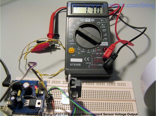
The closer the object the bigger the angle and this also produce the bigger voltage output through the sharp GP2D120 Vo pin and vise versa. By connecting the sharp GP2D120 output pin (Vo, pin 1) to the PIC16F690 microcontroller RA4 analog input port (ADC channel 3), we could easily use the PIC16F690 ADC peripheral to determine the object distance.
Because BRAM is move both to the left and right, for proper alignment according to the sharp GP2D120 datasheet you should place the GP2D120 sensor vertical towards the moving object as shown on this picture bellow (taken from sharp GP2D120 datasheet).

The maximum effective range that can be measured by sharp GP2D120 is less than 30 cm, for longer range, you could use the other member of sharp GP2X distance measurement sensor families such as sharp GP2Y0A02YK, GP2Y0A21YK and GP2Y0A700K0F.
The Final BRAM
For the final BRAM program I decide to add one more behavior to BRAM using the Sharp GP2D120 distance sensor and two LEDs for the BRAM’s beacon using the PIC16F690 microcontroller TIMER0 peripheral. In order to make the program more structured and easy to be modified for the new behavior in the future, in this final program, BRAM fully implement the program fixed priority selector and each of BRAM behavior will have their own unique control over BRAM steer, speed and head light.


The following is the C code of the final BRAM brain implementation:
// *****************************************************************************
//  File Name    : brampicphoto.c
//  Version      : 2.0
//  Description  : BRAM - Beginner's Robot Autonomous Mobile
//                 PIC Photovore II
//  Author       : RWB
//  Target       : PICJazz 16F690 Board
//  Compiler     : HI-TECH C PRO for the PIC10/12/16 MCU family V9.60PL5 (Lite)
//  IDE          : Microchip MPLAB IDE v8.30
//  Programmer   : PICKit2
//  First Version: 05 May 2009
//                 - Showing Basic Behavior Based Intelligent
//  Last Updated : 18 May 2009
//                 - Adding Sharp GPD2D120 Distance Measurement Sensor
//                 - Adding Beacon LED using TIMER0
//                 - Modified Program to use the Behavior Priority Selector
// *****************************************************************************
#include <pic.h>
#include <stdlib.h>
#include <stdio.h>
/*   PIC Configuration Bit:
**   INTIO     - Using Internal RC No Clock
**   WDTDIS    - Wacthdog Timer Disable
**   PWRTEN    - Power Up Timer Enable
**   MCLREN    - Master Clear Enable
**   UNPROTECT - Code Un-Protect
**   UNPROTECT - Data EEPROM Read Un-Protect
**   BORDIS    - Borwn Out Detect Disable
**   IESODIS   - Internal External Switch Over Mode Disable
**   FCMDIS    - Monitor Clock Fail Safe Disable
*/
__CONFIG(INTIO & WDTDIS & PWRTEN & MCLREN & UNPROTECT \
  & UNPROTECT & BORDIS & IESODIS & FCMDIS);
// Using Internal Clock of 8 MHz
#define FOSC 8000000L
// Define Light Parameter
#define LIGHT_THRESHOLD  30
#define THRESHOLD_VALUE  50
#define MAX_THRESHOLD    180
// Define IR Parameter
#define MIN_DISTANCE  90
// Define BRAM Steering
#define MOVE_FORWARD  0
#define TURN_LEFT     1
#define TURN_RIGHT    2
#define ROTATE_LEFT   3
#define ROTATE_RIGHT  4
#define MOVE_BACKWARD 5
#define FULL_STOP     6
// Define BRAM Behavior Priority ID
#define NO_ACTIVITY     0
#define BUMP_AVOIDANCE  1
#define IR_AVOIDANCE    2
#define LIGHT_AVOIDANCE 3
#define LIGHT_FOLLOWER  4
#define EXPLORING       5
#define MAX_BEHAVIOR    6
#define MAX_STEER_PARAM 4
unsigned char behavior_ctrl[MAX_BEHAVIOR];
unsigned char steer_ctrl[MAX_BEHAVIOR][MAX_STEER_PARAM];
unsigned int  steer_delay[MAX_BEHAVIOR][MAX_STEER_PARAM];
unsigned char steer_speed[MAX_BEHAVIOR][MAX_STEER_PARAM];
unsigned char steer_count[MAX_BEHAVIOR];
unsigned char head_light[MAX_BEHAVIOR];
unsigned char speed;                // Default Speed Variable
unsigned char halt_status;
unsigned char c1,c2;
// BRAM Debugging Mode, 0 - Debug Off, 1 - Debug On
#define BRAM_DEBUG    1
#if BRAM_DEBUG
  #define BAUD_RATE 9600
#endif
// Delay Function
#define	_delay_us(x) { unsigned char us; \
			         us = (x)/(12000000/FOSC)|1; \
			         while(--us != 0) continue; }
void _delay_ms(unsigned int ms)
{
  unsigned char i;
  do {
    i = 4;
    do {
      _delay_us(164);
    } while(--i);
  } while(--ms);
}
static void interrupt isr(void)
{
  static unsigned int beacon_on = 0;
  static unsigned int beacon_off = 0;
  if(T0IF) {			    // TIMER0 Interrupt Flag
    if (beacon_on > 4000) {
      RA2=1;
      beacon_off++;
    } else {
      beacon_on++;
    }
    if (beacon_off > 800) {
      RA2=0;
      beacon_off=0;
      beacon_on=0;
    }
    TMR0 = 156;             // Initial Value for 0.1ms Interrupt
    T0IF = 0;			    // Clear TIMER0 interrupt flag
  }
}
// BRAM UART Debugging Function
#if BRAM_DEBUG
void ansi_cl(void)
{
  // ANSI clear screen: cl=\E[H\E[J
  putchar(27);
  putchar('[');
  putchar('H');
  putchar(27);
  putchar('[');
  putchar('J');
}
void ansi_me(void)
{
  // ANSI turn off all attribute: me=\E[0m
  putchar(27);
  putchar('[');
  putchar('0');
  putchar('m');
}
void ansi_cm(unsigned char row,unsigned char col)
{
  // ANSI cursor movement: cl=\E%row;%colH
  putchar(27);
  putchar('[');
  printf("%d",row);
  putchar(';');
  printf("%d",col);
  putchar('H');
}
void uart_init(void)
{
  TRISB5 = 1;          // Set Port B5 and B7 for UART Tx and Rx
  TRISB7 = 0;
  // Baud Rate formula for SYNC=0 (Async), BRG16=0 (8-bit), BRGH=0 (low speed)
  // 0.16% Error for 8 Mhz Oscilator Clock. Actual Rate will be 9615.
  // BAUD_RATE = FOSC / (64 x (SPBRG + 1))

  SPBRG = (int)(FOSC/(64UL * BAUD_RATE)) - 1;
  TXSTA = 0b00100000;  // Async, 8 bit and Enable Transmit (TXEN=1)
  RCSTA = 0b10010000;  // Serial Port Enable, Async,8-bit and Enable Receipt (CREN=1)
  BAUDCTL=0;
}
void putch(unsigned char data)
{
  // Send Data when TXIF bit is ready
  while(!TXIF) continue;
  TXREG = data;
}
unsigned char getch(void) {
  // Get Data when RCIF bit is ready
  while(!RCIF) continue;
  return RCREG;
}
#endif
// BRAM Speed and Steering Functions
void BRAM_speed(unsigned char sp)
{
  // Adjust the PWM CCPR1L register
  CCPR1L=sp;
}
void BRAM_steer(unsigned char steer)
{
  switch(steer) {
    case MOVE_FORWARD:
      RC4=0; RC5=1;  // Right Motor On Forward
      RC6=1; RC7=0;  // Left Motor On Forward
      break;
    case TURN_LEFT:
      RC4=0; RC5=1;  // Right Motor On Forward
      RC6=0; RC7=0;  // Left Motor Off
      break;
    case TURN_RIGHT:
      RC4=0; RC5=0;  // Right Motor Off
      RC6=1; RC7=0;  // Left Motor On Forward
      break;
    case ROTATE_LEFT:
      RC4=0; RC5=1;  // Right Motor On Forward
      RC6=0; RC7=1;  // Left Motor On Reverse
      break;
    case ROTATE_RIGHT:
      RC4=1; RC5=0;  // Right Motor On Reverse
      RC6=1; RC7=0;  // Left Motor On Forward
      break;
    case MOVE_BACKWARD:
      RC4=1; RC5=0;  // Right Motor On Reverse
      RC6=0; RC7=1;  // Left Motor On Reverse
      break;
    case FULL_STOP:
      RC4=0; RC5=0;  // Right Motor Off
      RC6=0; RC7=0;  // Left Motor Off
      break;
  }
}
// BRAM Behaviour Functions
int random_number(void)
{
   unsigned char num;

   num=(unsigned char) rand();
   return ((num % 300) + 20);
}
void BRAM_BumpAvoidance(unsigned char bump_sensor)
{
  static unsigned char turn_status = 0;
  unsigned char cnt;
  turn_status ^= 0x01;
  behavior_ctrl[BUMP_AVOIDANCE]=0;
  head_light[BUMP_AVOIDANCE]=0;
  cnt=0;
#if BRAM_DEBUG
    ansi_cm(3,1);
    printf("Whisker Value: %03d",bump_sensor);
#endif
  // Process the Whisker Sensor
  if (bump_sensor > 50) {
    // Turn On BRAM Head Light
    head_light[BUMP_AVOIDANCE]=1;

    // Activate the Bump Avoidance Behavior
    behavior_ctrl[BUMP_AVOIDANCE]=1;
    // Initial Random Seed Number
    srand(bump_sensor);
    steer_ctrl[BUMP_AVOIDANCE][cnt]=FULL_STOP;
    steer_delay[BUMP_AVOIDANCE][cnt]=20;
    steer_speed[BUMP_AVOIDANCE][cnt]=0;
    cnt++;
    steer_ctrl[BUMP_AVOIDANCE][cnt]=MOVE_BACKWARD;
    steer_delay[BUMP_AVOIDANCE][cnt]=150;
    steer_speed[BUMP_AVOIDANCE][cnt]=speed - 5;
    cnt++;
    if (bump_sensor <= 120) {
      // Left Bump Switch Range: 0 to 120
      steer_ctrl[BUMP_AVOIDANCE][cnt]=ROTATE_RIGHT;
      steer_delay[BUMP_AVOIDANCE][cnt]=random_number();
      steer_speed[BUMP_AVOIDANCE][cnt]=speed;

    } else if (bump_sensor > 120 && bump_sensor <= 130) {
      // Right Bump Switch Range: 120 to 130
      steer_ctrl[BUMP_AVOIDANCE][cnt]=ROTATE_LEFT;
      steer_delay[BUMP_AVOIDANCE][cnt]=random_number();
      steer_speed[BUMP_AVOIDANCE][cnt]=speed;

    } else {
      // Left + Right Bump Switch: > 130
      if (turn_status)
        steer_ctrl[BUMP_AVOIDANCE][cnt]=ROTATE_LEFT;
      else
        steer_ctrl[BUMP_AVOIDANCE][cnt]=ROTATE_RIGHT;
      steer_delay[BUMP_AVOIDANCE][cnt]=random_number();
      steer_speed[BUMP_AVOIDANCE][cnt]=speed;
    }
    cnt++;
  }
  steer_count[BUMP_AVOIDANCE]=cnt;
}
void BRAM_IRAvoidance(unsigned char ir_sensor)
{
  static unsigned char turn_status = 0;
  static unsigned char obj_approach = 0;
  static unsigned char obj_count = 0;
  unsigned char cnt;
  turn_status ^= 0x01;
  behavior_ctrl[IR_AVOIDANCE]=0;
  head_light[IR_AVOIDANCE]=0;
  cnt=0;
#if BRAM_DEBUG
  ansi_cm(4,1);
  printf("GP2D120 Value: %03d",ir_sensor);
#endif
  if (ir_sensor > MIN_DISTANCE) {
    // Activate the IR Avoidance Behavior
    behavior_ctrl[IR_AVOIDANCE]=1;
    head_light[IR_AVOIDANCE]=1;
    // Initial Random Seed Number
    srand(ir_sensor);

    steer_ctrl[IR_AVOIDANCE][cnt]=FULL_STOP;
    steer_delay[IR_AVOIDANCE][cnt]=50;
    steer_speed[IR_AVOIDANCE][cnt]=0;
    cnt++;
    steer_ctrl[IR_AVOIDANCE][cnt]=MOVE_BACKWARD;
    steer_delay[IR_AVOIDANCE][cnt]=100;
    steer_speed[IR_AVOIDANCE][cnt]=speed - 5;
    cnt++;

    if (turn_status)
      steer_ctrl[IR_AVOIDANCE][cnt]=ROTATE_LEFT;
    else
      steer_ctrl[IR_AVOIDANCE][cnt]=ROTATE_RIGHT;
    steer_delay[IR_AVOIDANCE][cnt]=random_number();
    steer_speed[IR_AVOIDANCE][cnt]=speed;
    cnt++;
  }
  steer_count[IR_AVOIDANCE]=cnt;
}
void BRAM_LightAvoidance(unsigned char ldr_left, unsigned char ldr_right)
{
  static unsigned char turn_status = 0;
  unsigned char cnt;
  turn_status ^= 0x01;

  behavior_ctrl[LIGHT_AVOIDANCE]=0;
  head_light[LIGHT_AVOIDANCE]=0;
  cnt=0;
#if BRAM_DEBUG
  ansi_cm(5,1);
  printf("LA, Left LDR: %03d; Right LDR: %03d",ldr_left,ldr_right);
#endif
  if ((ldr_left > MAX_THRESHOLD) || (ldr_right > MAX_THRESHOLD)) {
    // Activate the Light Avoidance Behavior
    behavior_ctrl[LIGHT_AVOIDANCE]=1;
    steer_ctrl[LIGHT_AVOIDANCE][cnt]=FULL_STOP;
    steer_delay[LIGHT_AVOIDANCE][cnt]=200;
    steer_speed[LIGHT_AVOIDANCE][cnt]=0;
    cnt++;
    steer_ctrl[LIGHT_AVOIDANCE][cnt]=MOVE_BACKWARD;
    steer_delay[LIGHT_AVOIDANCE][cnt]=200;
    steer_speed[LIGHT_AVOIDANCE][cnt]=speed - 5;
    cnt++;
    if (turn_status)
      steer_ctrl[LIGHT_AVOIDANCE][cnt]=ROTATE_LEFT;
    else
      steer_ctrl[LIGHT_AVOIDANCE][cnt]=ROTATE_RIGHT;
    steer_delay[LIGHT_AVOIDANCE][cnt]=200;
    steer_speed[LIGHT_AVOIDANCE][cnt]=speed;
    cnt++;
  }
  steer_count[LIGHT_AVOIDANCE]=cnt;
}
void BRAM_LightFollower(unsigned char ldr_left, unsigned char ldr_right)
{
  int ldr_diff;
  unsigned char cnt;

  behavior_ctrl[LIGHT_FOLLOWER]=0;
  head_light[LIGHT_FOLLOWER]=0;
  cnt=0;
#if BRAM_DEBUG
  ansi_cm(6,1);
  printf("LF, Left LDR: %03d; Right LDR: %03d",ldr_left,ldr_right);
#endif
  // Get the different
  ldr_diff=ldr_left - ldr_right;
  if ((ldr_diff < -THRESHOLD_VALUE) || (ldr_diff > THRESHOLD_VALUE)) {
    // Activate the Light Follower Behavior
    behavior_ctrl[LIGHT_FOLLOWER]=1;
    if (ldr_diff < 0)
      steer_ctrl[LIGHT_FOLLOWER][cnt]=TURN_LEFT;
    else
      steer_ctrl[LIGHT_FOLLOWER][cnt]=TURN_RIGHT;
    steer_delay[LIGHT_FOLLOWER][cnt]=1;
    steer_speed[LIGHT_FOLLOWER][cnt]=speed;
    cnt++;
  }
  steer_count[LIGHT_FOLLOWER]=cnt;
}
void BRAM_Exploring(unsigned char ldr_left, unsigned char ldr_right)
{
  int ldr_diff;
  unsigned char cnt;

  behavior_ctrl[EXPLORING]=0;
  head_light[EXPLORING]=0;
  cnt=0;
#if BRAM_DEBUG
  ansi_cm(7,1);
  printf("EXP, Left LDR: %03d; Right LDR: %03d",ldr_left,ldr_right);
#endif
  // Get the different
  ldr_diff=ldr_left - ldr_right;
  if ((ldr_diff >= -THRESHOLD_VALUE) && (ldr_diff <= THRESHOLD_VALUE)) {
    // Activate the Exploring Behavior
    behavior_ctrl[EXPLORING]=1;

    steer_ctrl[EXPLORING][cnt]=MOVE_FORWARD;
    steer_delay[EXPLORING][cnt]=1;
    steer_speed[EXPLORING][cnt]=speed - 5;
    cnt++;
  }
  steer_count[EXPLORING]=cnt;
}
void BRAM_PrioritySelector(unsigned char halt_status)
{
  RA5=0;                  // BRAM Head Light Off
  for (c1=0; c1 < MAX_BEHAVIOR; c1++) {
    // Only Allowed one Behavior to Run
    if (behavior_ctrl[c1]) {
      RA5=head_light[c1];      // BRAM Head Light
      for (c2=0; c2 < steer_count[c1]; c2++) {
        BRAM_speed(steer_speed[c1][c2] * halt_status);
        BRAM_steer(steer_ctrl[c1][c2]);
        _delay_ms(steer_delay[c1][c2]);
      }
      return;
    }
  }
}
void BRAM_Reset()
{
  for (c1=0; c1 < MAX_BEHAVIOR; c1++) {
    behavior_ctrl[c1]=0;      // Not Active
    steer_count[c1]=0;
    head_light[c1]=0;         // Head Light Off
    for (c2=0; c2 < MAX_STEER_PARAM; c2++) {
      steer_ctrl[c1][c2]=FULL_STOP;
      steer_delay[c1][c2]=0;
      steer_speed[c1][c2]=0;  // Speed Stop
    }
  }
}
void main(void)
{
  unsigned char ldr_left;
  unsigned char ldr_right;
  unsigned char bump_sensor;
  unsigned char ir_sensor;
OSCCON=0x70; // Select 8 MHz internal clock
  TRISA = 0x13;        // Input for RA0,RA1 and RA4
  TRISC = 0x07;        // Set RC0,RC1 and RC2 as input others as Output
  ANSEL = 0x79;        // Set PORT AN0, AN3, AN4, AN5 and AN6 as analog input
  ANSELH = 0x00;       // Set PORT AN8 to AN11 as Digital I/O
  PORTC = 0x00;        // Turn Off all PORTC
  /* Init PWM for Single Output */
  CCP1CON=0b00001100;  // Single PWM mode; P1A, P1C active-high; P1B, P1D active-high
  CCPR1L=0;            // Start with zero Duty Cycle
  PSTRCON=0b00000100;  // Enable PIC Pulse Steering PWM on RC3 Port
  T2CON=0b00000101;    // Postscale: 1:1, Timer2=On, Prescale = 1:4
  PR2=0x65;            // Frequency: 4.90 kHz
  TMR2=0;              // Start with zero Counter

  /* Init ADC */
  ADCON1=0b00110000;   // Select the FRC for 8 MHz
  /* Init TIMER0: Period: Fosc/4 x Prescale x TMR0
     0.0005 ms x 2 * 100 = 0.1 ms */
  OPTION = 0b00000000; // 1:2 Prescaller
  TMR0=156;            // Interupt every 0.1 ms
  T0IE = 1;	       // Enable interrupt on TMR0 overflow
  GIE = 1;	       // Global interrupt enable
  // Initial all behaviour variables
  BRAM_Reset();
  halt_status=0;       // Initial: 0-Stop, 1-Run
  speed=0;             // Initial Speed
#if BRAM_DEBUG
  // Initial PIC16F690 UART
  uart_init();
  // Set the Attribute and Clear Screen
  ansi_me();
  ansi_cl();
  printf("Welcome to BRAM II Debugging Mode\n\r\n\r");
#endif
  // Blink BRAM's Head Light Twice for Ready
  RA5=1; _delay_ms(100);
  RA5=0; _delay_ms(100);
  RA5=1; _delay_ms(100);
  RA5=0; _delay_ms(100);
  // Beacon Off
  RA2=0;

  for(;;) {
    if (RA1 == 0) {           // BRAM Status Switch
      _delay_ms(1);
      if (RA1 == 0) {         // Read again for Simple Debounce
        halt_status ^= 0x01;  // Halt Status
      }
    }
    /* Start Read All the ADC input here */
    // The PWM Motor Speed Control
    ADCON0=0b00000001;        // Select Left justify result. ADC port channel AN0
    GODONE=1;	              // Initiate conversion on the channel 0
    while(GODONE) continue;   // Wait for conversion done
    speed=ADRESH;
    // Bumped Sensor
    ADCON0=0b00011001;       // Select left justify result. ADC port channel AN6
    GODONE=1;	             // Initiate conversion on the channel 6
    while(GODONE) continue;  // Wait for ldr_left conversion done
    bump_sensor=ADRESH;      // Read 8 bits MSB, Ignore 2 bits LSB in ADRESL

    // The LDR Sensor
    ADCON0=0b00010001;       // Select left justify result. ADC port channel AN4
    GODONE=1;	             // Initiate conversion on the channel 4
    while(GODONE) continue;  // Wait for ldr_left conversion done
    ldr_left=ADRESH;         // Read 8 bits MSB, Ignore 2 bits LSB in ADRESL
    ADCON0=0b00010101;       // Select left justify result. ADC port channel AN5
    GODONE=1;	             // Initiate conversion on the channel 5
    while(GODONE) continue;  // Wait for ldr_right conversion done
    ldr_right=ADRESH;        // Read 8 bits MSB, Ignore 2 bits LSB in ADRESL

    ADCON0=0b00001101;       // Select Left justify result. ADC port channel AN3
    _delay_us(10);
    GODONE=1;	             // Initiate conversion on the channel 3
    while(GODONE) continue;  // Wait for GP2D120 sensor conversion done
    ir_sensor=ADRESH;        // Read 8 bits MSB, Ignore 2 bits LSB in ADRESL
    ADCON0=0b00001101;       // Select Left justify result. ADC port channel AN3
    _delay_us(10);
    GODONE=1;	             // Initiate conversion on the channel 3
    while(GODONE) continue;  // Wait for GP2D120 sensor conversion done
    ir_sensor+=ADRESH;        // Read 8 bits MSB, Ignore 2 bits LSB in ADRESL

    // Run all BRAM's Behaviour
    // Bump Avoidance Behavior
    BRAM_BumpAvoidance(bump_sensor);
    // IR Avoidance Behavior
    BRAM_IRAvoidance(ir_sensor/2);
    // Light Avoidance Behavior
    BRAM_LightAvoidance(ldr_left,ldr_right);
    // Light Follower Behavior
    BRAM_LightFollower(ldr_left,ldr_right);
    // Exploring Behavior
    BRAM_Exploring(ldr_left,ldr_right);
    // Run BRAM Priority Selector
    BRAM_PrioritySelector(halt_status);
    // Reset All Behavior
    BRAM_Reset();
  }
}
/* EOF: brampicphoto.c */
The program’s principal is actually the same as the previous version (1.0), but instead of using fixed called to the BRAM steer, speed and head light; in this new version (2.0) I use the variables array to store each of the BRAM behavior actions and later on run all these behavior action using the BRAM_PrioritySelector() function. By using this new structure model, adding a new behavior become easier as we just adding the behavior action function and the behavior priority to the program.
If you notice from the code; the ADC value for sharp GP2D120 sensor is read twice; this to ensure that we get the valid value and pass the average value (divided by two) as the argument to the BRAM_IRAvoidance() function.
...
ADCON0=0b00001101;       // Select Left justify result. ADC port channel AN3
_delay_us(10);
GODONE=1;	         // Initiate conversion on the channel 3
while(GODONE) continue;  // Wait for GP2D120 sensor conversion done
ir_sensor=ADRESH;        // Read 8 bits MSB, Ignore 2 bits LSB in ADRESL
ADCON0=0b00001101;       // Select Left justify result. ADC port channel AN3
_delay_us(10);
GODONE=1;	         // Initiate conversion on the channel 3
while(GODONE) continue;  // Wait for GP2D120 sensor conversion done
ir_sensor+=ADRESH;       // Read 8 bits MSB, Ignore 2 bits LSB in ADRESL

// Run all BRAM's Behaviour
// Bump Avoidance Behavior
BRAM_BumpAvoidance(bump_sensor);
// IR Avoidance Behavior
BRAM_IRAvoidance(ir_sensor/2);
...
For more information about using the ADC peripheral on the Microchip PIC16F690 microcontroller you could refer to my previous posted blog PIC Analog to Digital Converter C Programming.
Other addition is the BRAM beacon; this beacon utilized the PIC16F690 TIMER0 interrupt which set to run on every 0.1 ms, for more information of using PIC16F690 TIMER0 you could refer to my previous posted blog Basic Servo Motor Controlling with Microchip PIC Microcontroller. The BRAM beacon is used to ensure that BRAM is still a live; make sure you use quite long cable to connect the LED, so you could place these two LED in any position around the BRAM’s body as you like.
The final program occupied about 87 % of the PIC16F690 flash ram using the HI-TECH C PRO for the PIC10/12/16 MCU family (Lite) V9.60PL5 compiler with DEBUG facility turn on (#define BRAM_DEBUG 1) and about 48 % if the DEBUG facility is turn off (#define BRAM_DEBUG 0); of course if you are using the HI-TEC C PRO in PRO mode the code will be 52 % smaller then the Lite mode shown here.

After rebuilding, debugging the code and download it to the PICJazz 16F690 board, now its time to watch BRAM final version in action:
Final Though
Another approach to the behavior base intelligent is introduced by Mike Tilden, using what he called Nervous Net which base on the couple stages of Octal Inverting Buffer (74AC240) combined with RC (resistor and capacitor) feedback circuit and connect directly to the DC motor; his method proved to work on the walker type robot and could simply handling various landscape without the need of microcontroller (it’s completely analog devices).
One of the latest interest projects on the machine’s intelligent development is the combination of real neuron tissue and mechanic used in the Gordon robot back in the middle of 2008; Gordon robot probably is the first living tissue neuron robot taken from rat’s brain. Because the living tissue can only survive inside the labs environment, therefore this living neuron communicates with its body (actuators and sensors) through the wireless protocol.
As you’ve seen from the video, the final BRAM show a quite complex behavior by combining all its behaviors; by using our imagination to interpret BRAM action, we could see that BRAM is try to be like a living animal that showing its existent in its simple world. Today although there is a lot improvement in the machine artificial intelligent research such as neuron networks, subsumption or the combination of both, but comparing to the “intelligent” shown by a small carbon based creature like bee or more complex creature such as bird, I think we still have a very long path just to match it.
Bookmarks and Share


Related Posts
19 Responses to “Behavior Based Artificial Intelligent Mobile Robot with Sharp GP2D120 Distance Measuring Sensor – BRAM Part 2”
Comment by neyo_napster.
is it possible to add another parameter to this existing bot..im planning to induce a voice path follow-up..will it crash the memory of the PIC16F690 due to overload..if so is there any alternative??
Comment by neyo_napster.
can u please explain more about IR avoidance behavior by the use of sharp GP2D120…if possible please attach a video explaining the behavior…thanks in advance!!!
Comment by rwb.
Actually the program only occupied 48% of the PIC 16F690 flash ram when the debugging mode is turn off, therefore there are still plenty flash for another behavior (parameter). Alternatively if you want to use the debugging mode, you could debug just your new behavior while turning off all other behavior.
IR avoidance principal is to use the position sensitive device such as sharp GP2D120 to measure the distance between the robot and the object (e.g. wall). As explained on this post the GP2D120 will return voltage level corresponding to the distance; therefore by knowing the distance between the robot and the measured object, we could decide a kind of behavior that the robot should behave. If you notice the video carefully sometimes you will see the robot avoid the wall before hitting it with its whisker.
Comment by EricTmz.
Hey,
I was trying to understand the L293D functionality and I think for your fig with “BRAM L293D Logic” there some problem with table…I think in the table..input 1 and 2 are deciding for right motor, and 3 and 4 are deciding for left motor which should be other way…I might be misunderstanding it..please let me know if that’s the case..thnaks
Comment by rwb.
Yes you are right, thank you. On the original picture RC4 (IN1),RC5 (IN2) should connected to the Right Motor while RC6 (IN3) and RC7 (IN4) should connected to the Left Motor. I’ve changed the “BRAM L293D Logic Control” picture so it showed the correct connection.
Comment by ppaul.
Hey , i am again :d.
I have a question . Can I use 2 output pwm to control the speed of the 2 dc motor?
Comment by rwb.
Sure you can. You could read this following article:
Building your own Simple Laser Projector using the Microchip PIC12F683 Microcontroller
Comment by ppaul.
Thanks . I managed the problem with 2 PWM CCP1 and CPP2.
Comment by ppaul.
I try to send data with com serial , and it’ works but when i use to receive data from computer with the function scanf() , give me a error
unsigned int i = 0;
scanf(“%03d”,&i); // give a error
printf(“Val%03d”,i); // work’s
Error [499] ; 0. undefined symbol:
_scanf(com_s_emicrobl.obj)
Can you explain me?
Thanks
Comment by rwb.
Note for the blog readers: @ppaul use Microchip PIC16F886 microcontroller which has two PWM peripherals i.e. CCP1 and CCP2.
About this Error:
Error [499] ; 0. undefined symbol: _scanf(com_s_emicrobl.obj)
It’s mean the scanf() function is not part of standard HI-TECH C Compiler library, use gets() function instead.
Comment by ppaul.
I try with getc , but not works . I see in manual of hi tech compiler the function sscanf . This function have more parameters and i not know to implement.
Thanks
Comment by rwb.
You should read the HI-TECH example program included in the HI-TECH C Compiler default installation here (assumed version 9.80) c:\Program Files\HI-TECH Software\PICC\9.80\samples\usart
Comment by ppaul.
Thanks . I find and implement and it’ works 😉
Comment by ppaul.
Hey ! You have a tutorial with implementing a PID controller?
Comment by rwb.
You could read this following article:
Build Your Own Microcontroller Based PID Control Line Follower Robot (LFR) – Second Part
Comment by adib.
i want ask you some question…i actually new student for electronic..course..and get assignment from my lecture…to create code(coding)….to servo motor move forward and reverse…otherwise if have some obstacle….that infrared sensor distance will detect and mobile robot will go other way….so i don’t no how to build code(assembler code) for this assignment….do you have some idea
Comment by rwb.
For the servo motor you could read this following article:
Basic Servo Motor Controlling with Microchip PIC Microcontroller

Comment by RajuDolly.
Very nice project. Thanks a lot
The way the project is explain is fantastic accompanied by well clear and high quality graphics.
Everything is clear and perfect
Very nice blog.
Thanks again and again
RajuDolly