Blog Entry
Introduction to the Embedded System with PICAXE Microcontroller
October 17, 2009 by rwb, under Microcontroller.
These days we are living and surrounding by many tiny computers called embedded products. Unlike the general purpose desktop computer that we use for browsing or typing our email, this tiny computer is designed to do only a limited specific task. We could easily found this embedded product just about anywhere such as home appliance (e.g. washing machine, refrigerator, microwave oven, TV/DVD), personal gadget (e.g. cell phone, MP3 players, digital camera), car (e.g. anti lock brake system, GPS navigation, alarm) and many more. The tremendous use of the embedded products in our daily life make the embedded system become one of the most important and interest subject to be learned.

Now come to the most asked question “How do I start it?” Actually when we learn the embedded system; we learn two things at the same time, the first one is the hardware which usually a microcontroller and the second one is the software to program the microcontroller to perform the desire task. Therefore most of the microcontroller manufacture already provides this learning tool all in one package (starter kits) to introduce their product to the microcontroller newcomer. Unfortunately most of this learning tool is aimed for the people that already have an adequate knowledge both in hardware and programming language.
Considering this need, many companies and the open source community start to offer their own embedded system development framework version, where this framework mostly aim for student, hobbyist and even to the professional.

Among these embedded system learning and development framework I found that the PICAXE from Revolution Education Ltd in UK (http://www.rev-ed.co.uk/picaxe) is one of the best in terms of price and ease to be used. Equipped with the free sophisticated PICAXE Programming Editor to program, debug, simulate and download the code to the PICAXE microcontroller; therefore this makes the PICAXE framework is a perfect choice for the embedded system newcomer.

The PICAXE Programming Editor also can automatically generate the BASIC program code base on the flowchart you draw.

The PICAXE microcontroller is based on various range of Microchip PIC microcontroller, start from 8 pins up to 40 pins PIC microcontroller.

The PICAXE Microcontroller
Unlike the other BASIC interpreter framework mention above which use the EEPROM to store the program, the PICAXE is a stand alone microcontroller solution, where both of program and the BASIC interpreter firmware is stored in the PIC microcontroller own memory (FLASH and/or EEPROM). Therefore the PICAXE only required a very view external electronic component in order to make it work.

In fact you could drop the 180 ohm resistor (connect pin 19 directly to TX) shown on the above schematic, which left only two resistors (22K and 10K) to make this PICAXE microcontroller a fully function embedded learning system. Connecting the RS232 DB-9 female connector to your computer COM port or USB to RS232 converter and you are ready to program this PICAXE microcontroller.

How ease to program this PICAXE microcontroller? To find it out, I did a small research; First I taught the fourth grade kid (9 years old) just an essential PICAXE BASIC (Beginner’s All-Purpose Symbolic Instruction Code) language commands to program the PICAXE microcontroller output which connected to four LED and let him play with it for a while; later on I asked him to program the PICAXE 20M using the AXEJazz 20PIN learning and development board from ermicro, so it could display the back and forth running LED. This is the PICAXE BASIC code that he came with and I called it “HelloWorld.bas” (I put some comments on the original code to make it clear).
'--------------------------------------------------------------------
' Program Name : HelloWorld.bas
' Description  : HelloWorld PICAXE Program
' Author       : TRB
' Target       : AXEJazz 20PIN Learning Board
' Interpreter  : PICAXE Firmware version 3.B
' IDE          : PICAXE Programming Editor Version 5.2.6
' Programmer   : PICAXE Programming Editor Version 5.2.6
' Last Update  : 15 Aug 2009
'--------------------------------------------------------------------
#picaxe 20M

symbol led7=7    ' LED7 Attached to PICAXE Output 7
symbol led6=6    ' LED6 Attached to PICAXE Output 6
symbol led5=5    ' LED5 Attached to PICAXE Output 5
symbol led4=4    ' LED5 Attached to PICAXE Output 5

main: high led7  ' Set High Output 7
      low led6   ' Set Low Output 6
      low led5   ' Set Low Output 5
      low led4   ' Set Low Output 4
      pause 100  ' Pause 100ms

      low led7
      high led6
      low led5
      low led4
      pause 100  ' Pause 100ms

      low led7
      low  led6
      high led5
      low led4
      pause 100  ' Pause 100ms

      low led7
      low led6
      low led5
      high led4
      pause 100  ' Pause 100ms

      low led7
      low led6
      high led5
      low led4
      pause 100  ' Pause 100ms

      low led7
      high led6
      low led5
      low led4
      pause 100  ' Pause 100ms

      goto main  ' Back to the main label
      end

' EOF: HelloWorld.bas
As you’ve seen from the code above, this is a simple endless loop program with contain only three PICAXE BASIC high, low and pause commands. Even though this program looks naïve to the more experience BASIC programmer, but it proves that programming the PICAXE microcontroller is not difficult. To read more about the PICAXE you could visit their website mention above; they have a very good PICAXE user manual and the PICAXE BASIC user reference.
The PICAXE Analog to Digital Converter
Using the same Input/Output circuit above, I enhanced the HelloWorld.bas program so we could control the LED display speed using the 10K trimport connected to the PICAXE Input 7 (ADC input) and at the same time reading the digital input connected to the PIXAXE Input 3 to change the LED display behavior
'***************************************************************************
'  File Name    : blinkled.bas
'  Version      : 1.0
'  Description  : PICAXE Blinking LED
'  Author       : RWB
'  Target       : AXEJazz 20PIN Learning Board
'  Interpreter  : PICAXE Firmware version 3.B
'  IDE          : PICAXE Programming Editor Version 5.2.6
'  Programmer   : PICAXE Programming Editor Version 5.2.6
'  Last Updated : 22 September 2009
'***************************************************************************
' Use PICAXE 20M
#picaxe 20M
' Assign Variables
symbol adc_val = b0  ' Use b0 for adc_val
symbol high_val = b1
symbol low_val = b2
symbol sign = b3
let pins = %00000000 ' Reset all Output Pins
sign = 0             ' Default Running LED
main:
  ' Read User Switch on Input IN3
  if pin3 = 0 then
    sign=sign XOR 1
  endif

  ' Read Trimport ADC Value on Input IN7
  readadc 7,adc_val

  if sign = 0 then
    for high_val = 4 to 7
      low_val=high_val - 1
      low low_val
      high high_val

      pause adc_val
    next high_val

    for high_val = 6 to 4 step -1
      low_val=high_val + 1
      low low_val
      high high_val

      pause adc_val
    next high_val
  else
    let pins = %11000000
    pause adc_val
    let pins = %00110000
    pause adc_val
  endif

  goto main      ' Back to the main loop
  end
' EOF: blinkled.bas
The trimport is used as the voltage divider circuit, where adjusting the trimport will varying the voltage on the PICAXE Input 7. Using the PICAXE BASIC readadc command we could easily capture the voltage changing and represent it in digital form (Analog to Digital Conversion). Then we use this ADC value to set the LED display delay using pause adc_val command. For comparison of how to do this ADC stuff in C language you could read my previous posted blog PIC Analog to Digital Converter C Programming.
By examining the PICAXE Input3 status (pin3), we could determine whether this pin is low (button pressed) or high (button release) and use this status to toggle the sign variable for different LED display behavior
' Read User Switch on Input IN3
if pin3 = 0 then
  sign=sign XOR 1
endif
The PICAXE BASIC interpreter use a predefined general purpose variables to store temporary data on the microcontroller RAM, these general purpose variables is called “bit” for 1-bit operation, “b” for 8-bit operation and “w” for 16-bit operation. The total variable that you could utilize is depending on the PICAXE type we use.

Using the PICAXE BASIC symbol command, we could redefine the variable name to become more readable instead of just using the b0, b1,b2 and b3 as shown on this following code:
' Assigned Variable
symbol adc_val = b0  ' Use b0 for adc_val
symbol high_val = b1
symbol low_val = b2
symbol sign = b3
The last is the let pins command, this special command is used to set or clear the PICAXE output port, therefore by assigning the pins with binary value of %00000000, means we clear all the PICAXE-20M output port (Output 0 to Output 7).
let pins = %00000000 ' Reset all Output Pins
Driving the Seven Segment Display with PICAXE
Driving the seven segment display is one of the basic knowledge that should be known when we learn the embedded system. Basically the seven segment display contain 7 LED plus 1 LED for the dot sign, therefore driving this seven segment display use the same principal as we drive an ordinary LED.

The following program show the counted number from 0 to 9 on the common cathode seven segment display:
'***************************************************************************
'  File Name    : sevenseg.bas
'  Version      : 1.0
'  Description  : PICAXE Seven Segment
'  Author       : RWB
'  Target       : AXEJazz 20PIN Learning Board
'  Interpreter  : PICAXE Firmware version 3.B
'  IDE          : PICAXE Programming Editor Version 5.2.6
'  Programmer   : PICAXE Programming Editor Version 5.2.6
'  Last Updated : 22 September 2009
'***************************************************************************
' Use PICAXE 20M
#picaxe 20M
' Assign Variables
symbol cnt = b0
symbol adc_val=b1
symbol seg_dot = 7
let pins = %00000000 ' Reset all Output Pins
main:
  for cnt=0 to 9
    readadc 7,adc_val  ' Read ADC Value on Input Port 7

    gosub disp_val
    pause adc_val
  next cnt

  ' Clear Output
  let pins = %00000000 ' Reset all Output Pins
  pause 100

  for cnt=0 to 2
    high seg_dot
    pause adc_val
    low seg_dot
    pause adc_val
  next cnt

  goto main      ' Back to main loop
  end
disp_val:
  select cnt
    case 0
      let pins = %00111111     ' 0 -> A=1,B=1,C=1,D=1,E=1,F=1,G=0,DOT=0
    case 1
      let pins = %00000110     ' 1 -> A=0,B=1,C=1,D=0,E=0,F=0,G=0,DOT=0
    case 2
      let pins = %01011011     ' 2 -> A=1,B=1,C=0,D=1,E=1,F=0,G=1,DOT=0
    case 3
      let pins = %01001111     ' 3 -> A=1,B=1,C=1,D=1,E=0,F=0,G=1,DOT=0
    case 4
      let pins = %01100110     ' 4 -> A=0,B=1,C=1,D=0,E=0,F=1,G=1,DOT=0
    case 5
      let pins = %01101101     ' 5 -> A=1,B=0,C=1,D=1,E=0,F=1,G=1,DOT=0
    case 6
      let pins = %01111101     ' 6 -> A=1,B=0,C=1,D=1,E=1,F=1,G=1,DOT=0
    case 7
      let pins = %00000111     ' 7 -> A=1,B=1,C=1,D=0,E=0,F=0,G=0,DOT=0
    case 8
      let pins = %01111111     ' 8 -> A=1,B=1,C=1,D=1,E=1,F=1,G=1,DOT=0
    case 9
      let pins = %01101111     ' 9 -> A=1,B=1,C=1,D=1,E=0,F=1,G=1,DOT=0
 endselect
 return

' EOF: sevenseg.bas
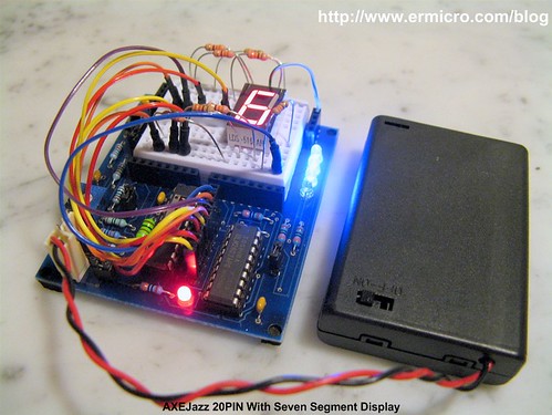
As you’ve seen from the code above, by controlling which of the LED segment to be displayed we could easily display the number on this seven segment display. For example if we want to display the value “6“, we could simply make the LED on segment A, C, D, E, F and G to illuminate. Here I used the PICAXE BASIC subroutine disp_val to do the seven segment display task, therefore by calling this subroutine with gosub command it will display the number on the seven segment display according to the cnt variable value. Again in this experiment the ADC (Input 7) is being used for controlling the display delay.
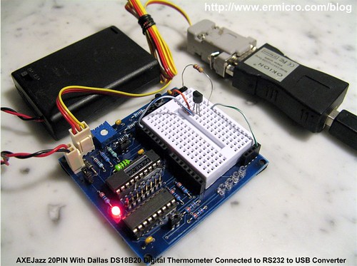
Connecting PICAXE with Dallas DS18B20 Digital Thermometer
On this last example, I will show you how ease to use Dallas DS18B20 digital thermometer with PICAXE microcontroller and at the same time we will use the serial (RS232) terminal to display the temperature result.

Dallas DS18B20 is a well known 1-Wire interface centigrade digital thermometer, this TO-92 package chip could measure temperature range from -55 centigrade degree to +125 centigrade degree and it only require 1 data line plus the ground to communicate with the microcontroller. Now take a look of how the PICAXE BASIC communicates with this sophisticated digital temperature sensor:
'***************************************************************************
'  File Name    : ds18b20.bas
'  Version      : 1.0
'  Description  : Temperature Sensor with Dallas DS18B20
'  Author       : RWB
'  Target       : AXEJazz 20PIN Learning Board
'  Interpreter   : PICAXE Firmware version 3.B
'  IDE          : PICAXE Programming Editor Version 5.2.6
'  Programmer   : PICAXE Programming Editor Version 5.2.6
'  Last Updated : 22 September 2009
'***************************************************************************
' Use PICAXE 20M
#picaxe 20M
' Assign Variables
symbol temp_val = b0
symbol row_pos = b1
symbol col_pos = b2
let pins = %00000000 ' Reset all Output Pins
' Initial ANSI Terminal
' Baud: 4800,Data: 8, Parity: None, Stop Bit: 1
gosub ansi_me
gosub ansi_cl
let row_pos=1
let col_pos=1
gosub ansi_cm
sertxd ("AXEJazz 20PIN - DS18B20 Digital Thermometer")
main:
  readtemp 1,temp_val  ' Read the DS18B20 Data Value

  let row_pos=3
  let col_pos=1
  gosub ansi_cm
  if temp_val <= 127 then
    sertxd ("Temperature: ",#temp_val," ",248,"C")
  else
    let temp_val = temp_val - 128
    sertxd ("Temperature: -",#temp_val," ",248,"C")
  endif

  pause 100

  goto main            ' Back to main loop
  end

ansi_me:
  ' ANSI turn off all attribute: me=\E[0m
  sertxd (27,"[0m")
  return

ansi_cl:
  ' ANSI clear screen: cl=\E[H\E[J
  sertxd (27,"[H",27,"[J")
  return
ansi_cm:
  ' ANSI cursor movement: cl=\E[%row;%colH
  sertxd (27,"[",#row_pos,";",#col_pos,"H")
  return
' EOF: ds18b20.bas
On this experiment we just use 8-bit precision (the eighth bit is used as a negative sign bit) temperature measurement using the PICAXE BASIC readtemp command which is especially designed function just for the Dallas DS18B20 chip; and when it’s done (approximately 750ms) then the 8-bit temp_val variable will be contained the exact room temperature measured by the DS18B20 chip. When the value reach 128, mean the room temperature is swing to negative (the eighth bit is logical “1“) then we subtract the value with 128 to get the exact negative value. Next we display this value to the serial terminal using the sertxd command.
You could use the Hyperterminal or puTTY program to display the room temperature and set the baud rate to 4800, 8-bit for the data width, none for the parity and 1-bit as the stop bit sign. Remember the PICAXE automatically use this setting when working with serial terminal, for 8 MHz PICAXE clock the baud rate will be automatically set to 9600.
Now you could enjoy seeing the whole PICAXE experiment we’ve done above on this following video:
The Final Though
The PICAXE actually show us how the technology could make our life easier, it just like when you want to copy a file on your desktop computer, you don’t have to type “copy source_directory\file_name target_directory\file_name“; instead on the modern computer operating system you just simply click “Copy” and click “Paste” the file. I bet many peoples on these days never use this old “copy” command anymore (they even don’t recognize that this command in fact is still exist). The same principal is shown on the PICAXE BASIC that we just use a simple command such as readadc to read the ADC value, readtemp to read the DS18B20 digital thermometer, servo to drive the servo motor and pwmout to produce the background PWM pulse.
Although the C and Assembler are still the main language choice when programming the embedded system because of their execution speed; but for many systems that only required low response time from the microcontroller; the PICAXE offer rapid and robust development framework to your embedded system application. The other alternative is; you could use the PICAXE microcontroller as your co-microcontroller to support your main microcontroller to do many various tasks such as servo controller, keypad reading, LCD or seven segment displayer or as the PWM source for your DC motor.
Bookmarks and Share


Comment by asterios.
Nice post! All info about PICAXE in one post, very interesting post.
Stavros