Blog Entry
Telepresence Robot using Microchip PIC16F1829 and Atmel AVR ATmega168 I2C Smart DC Motor Controller Microcontroller – Part 2
September 5, 2013 by rwb, under Robotics.
The I2C (read as I square C) smart DC motor controller is designed using the Atmel 8-bit AVR Atmega168 microcontroller and configured to act as the I2C slave device where it could be controlled by other microcontroller or microprocessor through the I2C SDA (serial data) and SCL (serial clock) interface. In the first part we have accomplished a basic DC motor controller tasks i.e. differential steering and speed control using pulse width modulation (PWM). In this second part article I will put all the features described in Building the I2C Smart DC Motor Controller with Atmel AVR Microcontroller article – Part 1, this mean we will adding more features to the I2C smart DC motor controller firmware which include wheel rotation and servo control.
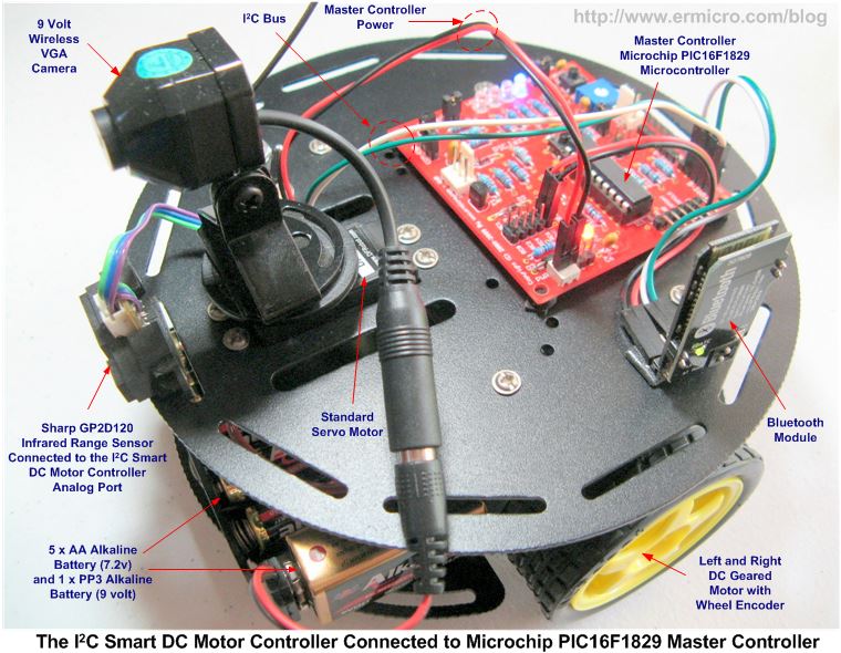
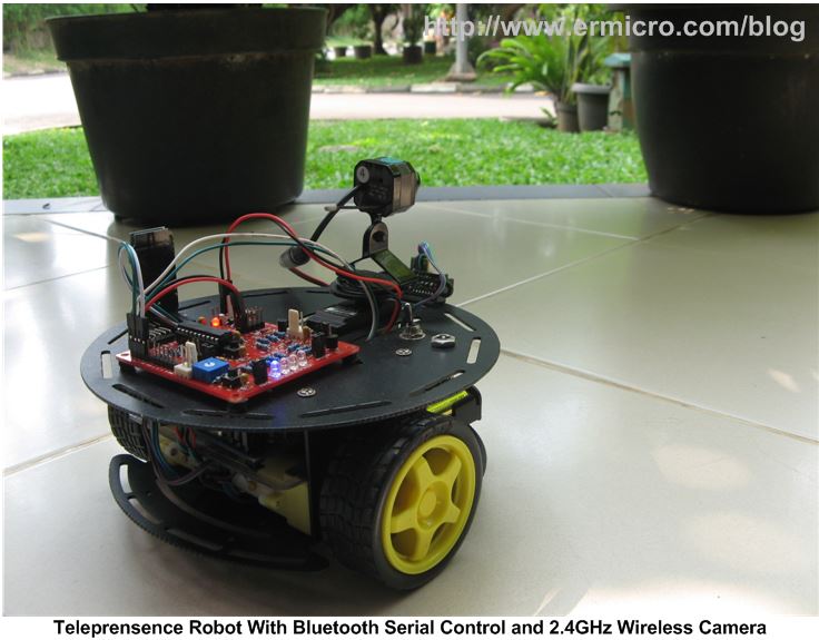
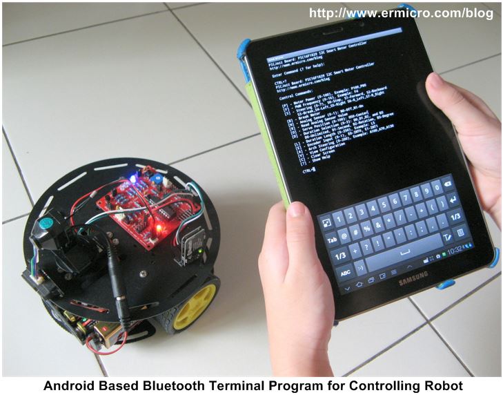
In order to make it more interesting and fun, in this part 2, I will build the telepresence robot which equipped with wireless serial protocol over Bluetooth, wireless 2.4Ghz camera mounted on the standard servo, and Sharp GP2D120 infrared range sensor as shown in this following picture.
The telepresence robot basically is a remote operating robot equipped with camera and sensors, therefore we could operate the robot from distance. Telepresence robot is used in many institutions in the world such academic/research, military, and space exploration to explore remote location or area where is too danger for human being to be present at that particular location.
Therefore as an electronics hobbyist building this kind of robot is just a dream in many years ago because it is expensive, but nowadays as more and more cheap and sophisticated wireless electronic modules are available in the market, now we could take part in the excitement of controlling this telepresence robot from our own mission control laptop at home as I did (see the video at the end of this article).
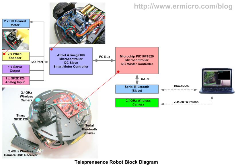
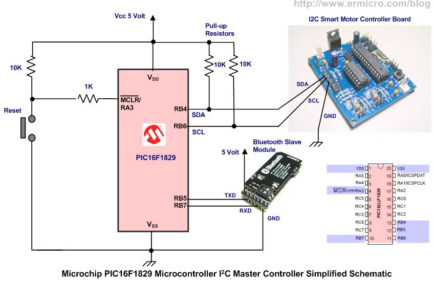
This articles also serve as a learning purpose of how we could combined two most popular 8-bit brand microcontrollers in the market i.e. 8-bit 20 pin PIC16F1829 microcontroller from Microchip as the I2C master controller where it will communicate through a serial Bluetooth protocol to a laptop and to the Atmel AVR ATmega168 microcontroller that serve as the I2C slave for controlling DC motors, servo, and reading an analog input. The following picture show the block diagram of the telepresence robot we will build in this article.
Ok let’s take a look at all the electronic components, modules and software required to develop this project:
1. The I2C Smart Motor Controller components as described in Building the I2C Smart DC Motor Controller with Atmel AVR Microcontroller – Part 1 and the electronic schematic
2. The PICJazz 20PIN Learning and Development Board with PIC16F1829 microcontroller from ermicro
3. Bluetooth serial module, I used CSR BC417143 Bluetooth chip module from DFRobot
4. 2 x Wheel Encoder Module, I used 3PA wheel encoder from DFRobot
5. Mini 2.4GHz Wireless Camera and USB DVR from ebay
6. Atmel AVR Studio 6.0 for coding and debugging environment
7. Atmel AVR Programmer such as Atmel mkII programmer to program the I2C Smart Motor Controller Firmware
8. Microchip MPLAB IDE version 8.86 for the I2C Master Controller
9. Microchip Serial Bootloader AN1310 v1.05r, to program the AVRJazz 20PIN board.
10. TeraTerm or PuTTy to communicate with the Serial Bluetooth
11. Web Cam Viewer, I used WebCamViewer v1.0 program from http://www.bustatech.com/
12. Microsoft Visual Studio 2012 Express for compiling and running the I2C Bluetooth Control application
13. Atmel AVR ATmega168, Microchip PIC16F1829, SN74LVC1G14, and L293D Datasheet.
The following is the complete C code for the I2C Smart Motor Controller using Atmel ATMega168 Microcontroller:
//***************************************************************************
//  File Name    : i2cmcont.c
//  Version      : 1.0
//  Description  : I2C Motor Controller Firmware
//  Author       : RWB
//  Target       : Atmel AVR ATmega168 Microcontroller
//  Compiler     : AVR-GCC 4.3.2; avr-libc 1.6.2 (WinAVR 20090313)
//  IDE          : Atmel AVR Studio 6.0
//  Programmer   : Atmel AVRISP mkII
//               : Atmel AVR Studio 6.0
//  Last Updated : 12 February 2013
//***************************************************************************
#define F_CPU 16000000UL   // Used 16MHz

// I2C Motor Control Debugging Mode, 0-Debug Off, 1-Debug On
#define I2C_MCTL_DEBUG 0

#include <avr/io.h>
#include <util/delay.h>
#include <compat/twi.h>
#include <avr/interrupt.h>

#if I2C_MCTL_DEBUG
#include <stdio.h>

#define BAUD_RATE 19200
#endif

// I2C Motor Address and Register Address
#define I2C_MCTL_ADDR 0x4E
#define I2C_MCTL_ID 0x40

// ATmega168 Microcontroller I2C Motor Control Implementation PORT
// PORTB: 0-SERVO, 1-PWM1, 2-PWM2, 3-MOSI, 4-MISO, 5-SCK, 6-EOSC1, 7-EOSC2
// PORTC: 0-ADD0, 1-ADD1, 2-ADD2, 3-ANA0, 4-SDA, 5-SCL, 6-Reset
// PORTD: 0-RX, 1-TX, 2-INT0, 3-INT1, 4-1A, 5-2A, 6-3A, 7-4A

// MCONTL - Motor Control Register Address
// BIT 2,1,0 - Steering: 000-Stop, 001-Forward, 010-Backward, 011-Break
//                       100-Turn Left, 101-Turn Right, 110-Rotate Left,
//                       111-Rotate Right
// BIT 4,3 - Duration: 00-Unlimited, 01-Second, 10-Rotation, 11-Degree
//     Used MDURH - Hold 8-bit Hold Duration High Byte
//          MDURL - Hold 8-bit Hold Duration Low Byte
// BIT 5   - Next Action: 0 - Break, 1 - Coast
// BIT 6   - Rotation Sensor Input: 0 - INT0, 1 - INT1
// BIT 7   - ADC: 0 - Off, 1 - On
//
#define MCONTL 0x00
volatile uint8_t motor_contl = 0x00; // Motor Control Data Register

// MECONT - Extended Motor Control Register Address
// BIT 0   - 0 - Turn Off Servo Control on DIG0, 1 - Turn ON Servo Control on DIG0
// BIT 2,1 - 00 - Nothing, 01 - Position, 10 - CCW, 11 - CCW
// BIT 3-7 - Reserve
#define MECONT 0x01
volatile uint8_t motor_econt = 0x00; // Extended Motor Control Data Register

#define MDURA 0x02
volatile uint8_t motor_dur = 0x01;   // Motor Duration 8-Bit Data Register

// MSTEER - Motor Steering Register Address
// Value: 0 to 200, Default: 100: Motor A and B will get 100% From Power
//        100%         100%
// (A) ----------0----------- (B)
//               |
//              100
//
#define MSTEER 0x03
volatile uint8_t motor_steer = 100; // Motor Steer Data Register

// MPOWER - Motor Power Register Address
// Value: 0 to 100
// This Register will automatically write to MPWMA and MPWMB registers
#define MPOWER 0x04
volatile uint8_t motor_pwr = 100;   // Motor A/B Power Data Register

// MPWMA - Motor A PWM Register Address
// Value: 0 to 100
#define MPWMA 0x05
volatile uint8_t pwm_a = 100;       // Motor A PWM Data Register

// MPWMB - Motor B PWM Register Address
// Value: 0 to 100
#define MPWMB 0x06
volatile uint8_t pwm_b = 100;       // Motor B PWM Data Register

// MPWMFR - Motor PWM Frequency Register Address
// Value: 0 to 16: 0x00 - 200 Hz, 0x01 - 400 Hz,0x02 - 500 Hz, 0x03 - 1000 Hz
//                 0x04 - 2,000 Hz, 0x05 - 4,000 Hz, 0x06 - 8,000 Hz, 0x07 - 10,000 Hz
//                 0x08 - 12,500 Hz, 0x09 - 15,625 Hz, 0x0A - 20,000 Hz, 0x0B - 21,505 Hz
//                 0x0C - 22,471 Hz, 0x0D - 23,668 Hz, 0x0E - 24,096 Hz, 0x0F - 25,000 Hz
// Default Value: 0x04 (2 kHz)

#define MPWMFR 0x07
volatile uint8_t pwm_frq = 0x04;    // PWM Frequency Data Register

// MADCH/L - Motor ADC High/Low Byte Output Register Address
#define MADCH 0x08
#define MADCL 0x09
volatile uint8_t adc_high = 0x00;   // ADC High Byte Data Register
volatile uint8_t adc_low = 0x00;    // ADC Low Byte Data Register

// MERES - Motor Encoder Resolution Register Address
#define MERES 0x0A
volatile uint8_t encoder_rres = 20;  // Default 20 PPR (Pulse per Rotation)

// SMPOS - Servo Motor Position (0 - 100)
// Servo definition and variables
#define MAX_VALUE 2000
#define CCW_SERVO 100
#define CW_SERVO 0
#define CENTER_SERVO 50

volatile uint16_t servo_period=0;
volatile uint8_t servo_on=0;
volatile uint8_t servo_pos=0;

#define SMPOS 0x0B
volatile uint8_t smotor_pos = CENTER_SERVO; // Default Servo on Center

// IC1R (PWM Top)
volatile uint16_t pwm_top[16]={40000,20000,16000,8000,4000,2000,1000,800,640,512,400,372,356,338,332,320};
volatile uint16_t pwm_duty[16]={400,200,160,80,40,20,10,8,6,5,4,4,4,3,3,3};

// Define The I2C Motor Differential Steering
#define FULL_STOP     0
#define MOVE_FORWARD  1
#define MOVE_BACKWARD 2
#define FULL_BREAK    3
#define TURN_LEFT     4
#define TURN_RIGHT    5
#define ROTATE_LEFT   6
#define ROTATE_RIGHT  7

// I2C Motor Controller Register variables
volatile uint8_t regaddr,regdata;
volatile uint8_t count_dur;

#if I2C_MCTL_DEBUG
// UART Functions
void uart_init(void)
{
  UBRR0H = (((F_CPU/BAUD_RATE)/16)-1)>>8;      // Set baud rate
  UBRR0L = (((F_CPU/BAUD_RATE)/16)-1);
  UCSR0B = (1<<RXEN0)|(1<<TXEN0);           // Enable Rx & Tx
  UCSR0C=  (1<<UCSZ01)|(1<<UCSZ00);              // Set USART; 8N1
}

void uart_flush(void)
{
  unsigned char dummy;

  while (UCSR0A & (1<<RXC0)) dummy = UDR0;
}

int uart_putch(char ch,FILE *stream)
{
   if (ch == '\n')
    uart_putch('\r', stream);

   while (!(UCSR0A & (1<<UDRE0)));
   UDR0=ch;

   return 0;
}

int uart_getch(FILE *stream)
{
   unsigned char ch;

   while (!(UCSR0A & (1<<RXC0)));
   ch=UDR0;

   // Echo the Output Back to terminal
   uart_putch(ch,stream);

   return ch;
}
#endif

void MotorPWM(uint8_t msel)
{
  if (msel == 0x00) {
    OCR1A=pwm_top[pwm_frq] - (pwm_duty[pwm_frq] * pwm_a); // Set the Motor A Duty Cycle
  } else {
    OCR1B=pwm_top[pwm_frq] - (pwm_duty[pwm_frq] * pwm_b); // Set the Motor B Duty Cycle
  }
}

void MotorPower(void)
{
  pwm_a=motor_pwr;
  MotorPWM(0);        // Set Motor A PWM
  pwm_b=motor_pwr;
  MotorPWM(1);        // Set Motor B PWM
}

void MotorSteering(void)
{
#if I2C_MCTL_DEBUG
  printf("Motor Steering: %d\n",motor_steer);
#endif

  // Stright: Motor A Power equal Motor B Power
  if (motor_steer == 100) {
    MotorPower();
    return;
  }

  // Diferention Steering Here, Reduce PWR for particular motor
  if (motor_steer > 100) {
    // Arch Right: Reduce Motor B Power, While Keep Motor A Power as it
    pwm_a=motor_pwr;
    pwm_b=((200 - motor_steer) * motor_pwr) / 100;
  } else {
    // Arch Left: Reduce Motor A Power, While Keep Motor B Power as it
    pwm_a=(motor_steer * motor_pwr) / 100;
    pwm_b=motor_pwr;
  }
  MotorPWM(0);        // Set Motor A PWM
  MotorPWM(1);        // Set Motor B PWM
}

void MotorDirection(uint8_t msteer)
{
#if I2C_MCTL_DEBUG
  printf("Motor Direction: %d\n",msteer);
#endif
  switch(msteer) {
    case FULL_STOP:
      PORTD &= ~(1 << PD4); PORTD &= ~(1 << PD5); // Motor A Stop
      PORTD &= ~(1 << PD6); PORTD &= ~(1 << PD7); // Motor B Stop
      break;
    case MOVE_FORWARD:
      PORTD &= ~(1 << PD4); PORTD |= (1 << PD5);  // Motor A On Forward
      PORTD &= ~(1 << PD6); PORTD |= (1 << PD7);  // Motor B On Forward
      break;
    case MOVE_BACKWARD:
      PORTD |= (1 << PD4); PORTD &= ~(1 << PD5);  // Motor A On Reverse
      PORTD |= (1 << PD6); PORTD &= ~(1 << PD7);  // Motor A On Reverse
      break;
    case FULL_BREAK:
      PORTD |= (1 << PD4); PORTD |= (1 << PD5);   // Motor A Break
      PORTD |= (1 << PD6); PORTD |= (1 << PD7);   // Motor B Break
      break;
    case TURN_LEFT:
      MotorPower();
      PORTD &= ~(1 << PD4); PORTD |= (1 << PD5);  // Motor A On Forward
      PORTD &= ~(1 << PD6); PORTD &= ~(1 << PD7); // Motor B Off
      break;
    case TURN_RIGHT:
      MotorPower();
      PORTD &= ~(1 << PD4); PORTD &= ~(1 << PD5); // Motor A Off
      PORTD &= ~(1 << PD6); PORTD |= (1 << PD7);  // Motor B On Forward
      break;
    case ROTATE_LEFT:
      MotorPower();
      PORTD &= ~(1 << PD4); PORTD |= (1 << PD5);  // Motor A On Forward
      PORTD |= (1 << PD6); PORTD &= ~(1 << PD7);  // Motor B On Reverse
      break;
    case ROTATE_RIGHT:
      MotorPower();
      PORTD |= (1 << PD4); PORTD &= ~(1 << PD5);  // Motor A On Reverse
      PORTD &= ~(1 << PD6); PORTD |= (1 << PD7);  // Motor B On Forward
      break;
  }
}

void MotorDuration(void)
{
#if I2C_MCTL_DEBUG
   printf("Motor Duration: %d\n",((motor_contl & 0x18) >> 3));
#endif
  // Get the Motor Duration Control Bits
  switch((motor_contl & 0x18) >> 3) {
    case 0x00:                   // Unlimited Rotation
      EIMSK = 0x00;           // Disable External INT1 and INT0
      TIMSK0 &= ~(1<<OCIE0A);     // Disable TIMER0 Compare A Interrupt
      break;
    case 0x01:                   // Based on Second
      EIMSK = 0x00;           // Disable External INT1 and INT0
      TCNT0=0;
      TIFR0=(1<<OCF0A);       // Clear any pending Compare A Interrupt
      TIMSK0 |= (1<<OCIE0A);  // Enable TIMER0 Compare A Interrupt
      count_dur=0;
      break;
    case 0x02:                   // Based on Wheel Rotation
      TIMSK0 &= ~(1<<OCIE0A); // Disable TIMER0 Compare A Interrupt
      if ((motor_contl & 0x40)) {
        EIMSK |= (1<<INT1);   // Enable External Interrupt INT1
      } else {
        EIMSK |=(1<<INT0);    // Enable External Interrupt INT0
      }
      break;
    case 0x03:                // Based on Wheel Rotation Degree
      TIMSK0 &= ~(1<<OCIE0A); // Disable TIMER0 Compare A Interrupt
      if ((motor_contl & 0x40)) {
        EIMSK = (1<<INT1);    // Enable External Interrupt INT1
      } else {
        EIMSK =(1<<INT0);     // Enable External Interrupt INT0
      }
      break;
  }

  // Set Motor Direction
  MotorDirection((motor_contl & 0x07));
}

void ControlAction(uint8_t rw_status)
{

#if I2C_MCTL_DEBUG
  printf("Register Address: %x\n",regaddr);
  printf("Register Data: %x\n",regdata);
#endif

  // rw_status: 0-Read, 1-Write
  switch(regaddr) {
    case MCONTL:
      if (rw_status) {
        motor_contl=regdata;   // Write to Motor Control Register
       MotorDuration();     // Set Motor Duration

    // Turn On/Off ADC Feature
    if ((motor_contl & 0x80)) {
      // Enable ADC Peripheral
      ADCSRA |= (1 << ADEN);
    } else {
      // Disable ADC Peripheral
      ADCSRA &= ~(1 << ADEN);
        }
      } else {
      regdata=motor_contl;  // Read from Motor Control Register
      }
      break;
    case MECONT:
      if (rw_status) {
        motor_econt=regdata;  // Write to Extended Motor Control Register
    // Turn On/Off Servo Feature
    if ((motor_econt & 0x01)) {
      servo_period=0;         // Reset Servo Period Count
          servo_on=0;             // Reset Servo On Period Count
          servo_pos=smotor_pos;   // Assigned Servo Position

      TCNT2=0;                // Start counter at 0
      TIFR2=(1<<OCF2A);       // Clear any pending TIMER2 Compare A Interrupt
      TIMSK2 = (1<<OCIE2A);   // Enable TIMER2 Compare A Interrupt
    } else {
          TCNT2=0;                // Start counter at 0
      TIMSK2 &= ~(1<<OCIE2A); // Disable TIMER2 Compare A Interrupt
    }
      } else {
        regdata=motor_econt;  // Read from Extended Motor Control Register
      }
      break;
    case MDURA:
      if (rw_status) {
     motor_dur=regdata;    // Write to Motor Duration Register
     } else {
       regdata=motor_dur;    // Read from Motor Duration Register
     }
     break;
    case MSTEER:
      if (rw_status) {
    motor_steer=regdata;  // Write to Motor Steering register
    if (motor_steer > 200) motor_steer = 100;
    MotorSteering();      // Set Motor A and Motor B Steering
      } else {
    regdata=motor_steer;  // Read from Motor Steering register
      }
      break;
    case MPOWER:
      if (rw_status) {
    motor_pwr=regdata;    // Write to Motor Power register
    if (motor_pwr > 100) motor_pwr = 100;
    MotorPower();       // Set Motor Power to Motor A and Motor B
      } else {
    regdata=motor_pwr;    // Read from Motor Power register
      }
      break;
    case MPWMA:
      if (rw_status) {
    pwm_a=regdata;       // Write to PWMA register
    if (pwm_a > 100) pwm_a = 100;
        MotorPWM(0);         // Set PWM On Motor A
      } else {
    regdata=pwm_a;       // Read from PWMA register
      }

      break;
    case MPWMB:
      if (rw_status) {
     pwm_b=regdata;       // Write to PWMB register
     if (pwm_b > 100) pwm_b = 100;
     MotorPWM(1);         // Set PWM On Motor B
      } else {
     regdata=pwm_b;       // Read from PWMB register
      }
      break;
    case MPWMFR:
      if (rw_status) {
     pwm_frq=regdata;     // Write to PWM Frequency register

     // Stop the Motor
     MotorDirection(FULL_STOP);

        // Change the PWM Frequency
    ICR1=pwm_top[pwm_frq];
        MotorPWM(0);
        MotorPWM(1);
      } else {
    regdata=pwm_frq;     // Read from PWM Frequency register
      }
      break;
    case MADCH:
      if (rw_status == 0) {
    regdata=adc_high;    // Read from ADC High Byte Data register
      }
      break;
    case MADCL:
      if (rw_status == 0) {
    regdata=adc_low;     // Read from ADC Low Byte Data register
      }
      break;
    case MERES:
      if (rw_status) {
    encoder_rres=regdata; // Write To Encoder Rotation Resolution Data register
      } else {
    regdata=encoder_rres; // Read from Encoder Rotation Resolution Data register
      }
      break;
    case SMPOS:
      if (rw_status) {
      if (regdata >= 100) {
        smotor_pos = 200;     // Maximum Servo Motor Position: 200 x 0.01ms = 20ms
          } else {
          smotor_pos=100 + regdata; // Write To Servo Motor Position register
          }

      TCNT2=0;                // Start counter at 0
      TIFR2=(1<<OCF2A);       // Clear any pending TIMER2 Compare A Interrupt
          servo_period=0;        // Rsset Servo Period Count
          servo_on=0;            // Reset Servo On Period Count
          servo_pos=smotor_pos;  // Assigned Servo Position

      } else {
      regdata=smotor_pos - 100;   // Read from Servo Motor Position Data register
      }
      break;
  }
}

ISR(TWI_vect)
{
   static uint8_t i2c_state;

   // Disable Global Interrupt
   cli();

   // Get TWI Status Register, mask the prescaler bits (TWPS1,TWPS0)
   switch(TWSR & 0xF8) {
     case TW_SR_SLA_ACK:      // 0x60: SLA+W received, ACK returned
       i2c_state=0;           // Start I2C State for Register Address required

       TWCR |= (1<<TWINT);    // Clear TWINT Flag
       break;

     case TW_SR_DATA_ACK:     // 0x80: data received, ACK returned
       if (i2c_state == 0) {
         regaddr = TWDR;      // Save data to the register address
      i2c_state = 1;
       } else {
      regdata = TWDR;      // Save to the register data
      i2c_state = 2;
       }

       TWCR |= (1<<TWINT);    // Clear TWINT Flag
    break;

     case TW_SR_STOP:        // 0xA0: stop or repeated start condition received while selected
       if (i2c_state == 2) {
      ControlAction(1);    // Call Write I2C Action (rw_status = 1)
      i2c_state = 0;             // Reset I2C State
    }

    TWCR |= (1<<TWINT);    // Clear TWINT Flag
    break;
     case TW_ST_SLA_ACK:      // 0xA8: SLA+R received, ACK returned
     case TW_ST_DATA_ACK:     // 0xB8: data transmitted, ACK received
       if (i2c_state == 1) {
      ControlAction(0);    // Call Read I2C Action (rw_status = 0)

      TWDR = regdata;      // Store data in TWDR register
      i2c_state = 0;             // Reset I2C State
       }

       TWCR |= (1<<TWINT);       // Clear TWINT Flag
       break;

     case TW_ST_DATA_NACK:    // 0xC0: data transmitted, NACK received
     case TW_ST_LAST_DATA:      // 0xC8: last data byte transmitted, ACK received
     case TW_BUS_ERROR:       // 0x00: illegal start or stop condition
     default:
    TWCR |= (1<<TWINT);    // Clear TWINT Flag
    i2c_state = 0;         // Back to the Beginning State
   }

   // Enable Global Interrupt
   sei();
}

ISR(TIMER0_COMPA_vect)
{
  static uint8_t tcount=0;

  // Count to 100 for 1 Second timing: 100 x 10ms = 1s
  if (++tcount >= 100)  {
    tcount=0x00;          // Reset 1 Second Timing Counter
    if (++count_dur >= motor_dur) {
      TIMSK0 &= ~(1<<OCIE0A);   // Disable TIMER0 Compare A Interrupt
      if ((motor_contl & 0x20)) {
     MotorDirection(FULL_STOP);
      } else {
     MotorDirection(FULL_BREAK);
      }
      count_dur=0x00;
    }
  }

  TCNT0=0;                       // Reset TIMER0 Counter
  TIFR0=(1<<OCF0A);           // Clear any pending TIMER0 Compare A Interrupt
}

ISR(TIMER2_COMPA_vect)
{
  static uint8_t servo_stat=0;

  // MAX_VALUE is a Servo PWM Period: 2000 x 0.01ms = 20 ms
  if (++servo_period >= MAX_VALUE) {
    servo_period=0;
    servo_on=0;
    servo_stat=1;

    // Turn On PB0 (DIG0) every 20ms
    PORTB |= (1 << PB0);
  }

  if (servo_stat) {
    // servo_pos: 100 -> 100 x 0.01ms = 1.0ms, 200 -> 200 x 0.01ms = 2.0ms
    // 2ms -> CCW Rotation, 1ms -> CW Rotation
    if (++servo_on >= servo_pos) {
      // Turn Off PB0 (DIG0) every servo_pos count
      PORTB &= ~(1 << PB0);
      servo_on=0;
      servo_stat=0;
    }
  }

  TCNT2=0;                // Reset TIMER2 counter from 0
  TIFR2=(1<<OCF2B);       // Clear any pending TIMER2 Compare A Interrupt
}

ISR(INT0_vect)
{
  static uint8_t mpulse=0, rot=0;

  if (((motor_contl & 0x18) >> 3) == 0x03) {
    // Based on Wheel Rotation Degree
    if (++mpulse <= encoder_rres) {
      if (mpulse > motor_dur) {
        mpulse=0;
        EIMSK &= ~(1 << INT0);    // Disable Interrupt 0
        if ((motor_contl & 0x20)) {
          MotorDirection(FULL_STOP);
        } else {
          MotorDirection(FULL_BREAK);
        }
      }
    }
  } else {
    // Based on Wheel Rotation
    if (++mpulse >= encoder_rres) {
      mpulse=0;
        if (++rot >= motor_dur) {
        EIMSK &= ~(1 << INT0);    // Disable Interrupt 0
        if ((motor_contl & 0x20)) {
          MotorDirection(FULL_STOP);
        } else {
          MotorDirection(FULL_BREAK);
        }
        rot=0;
      }
    }
  }
}

ISR(INT1_vect)
{
  static uint8_t mpulse=0, rot=0;

  if (((motor_contl & 0x18) >> 3) == 0x03) {
    // Based on Wheel Rotation Degree
    if (++mpulse <= encoder_rres) {
      if (mpulse > motor_dur) {
        mpulse=0;
        EIMSK &= ~(1 << INT1);    // Disable Interrupt 1
        if ((motor_contl & 0x20)) {
          MotorDirection(FULL_STOP);
        } else {
          MotorDirection(FULL_BREAK);
        }
      }
    }
  } else {
    // Based on Wheel Rotation
    if (++mpulse >= encoder_rres) {
      mpulse=0;
      if (++rot >= motor_dur) {
        EIMSK &= ~(1 << INT1);    // Disable Interrupt 1
        if ((motor_contl & 0x20)) {
          MotorDirection(FULL_STOP);
        } else {
          MotorDirection(FULL_BREAK);
        }
        rot=0;
      }
    }
  }
}

// Used for Self Test and Debugging Function
void Write_I2CMCTL(uint8_t addr, uint8_t data)
{
  regaddr=addr;
  regdata=data;
  ControlAction(1);
}

#if I2C_MCTL_DEBUG

// Assign I/O stream to UART
FILE uart_str = FDEV_SETUP_STREAM(uart_putch, uart_getch, _FDEV_SETUP_RW);
#endif

int main(void)
{
  uint8_t i2c_address;
#if I2C_MCTL_DEBUG
  uint16_t adcval;
#endif

  DDRB = 0xFF;      // Set PORTB as Output
  PORTB = 0x00;     // Reset PORTB Output
  DDRC = 0x00;      // Set PORTC as Input
  PORTC = 0x07;     // Activate Pull-up on PORTC: 0,1,3
  DDRD = 0xF0;      // Set PORTD: 0,1,2,3 as input and PORTD 4,5,6,7 as Output
  PORTD = 0x0F;     // Set All PORTD 0,1,2,3 High and PORTD 4,5,6,7 to Low

#if I2C_MCTL_DEBUG
  // Define Output/Input Stream
  stdout = stdin = &uart_str;

  // Initial UART Peripheral
  uart_init();
#endif

  // Time Based Motor Control Initialization using TIMER0
  // TCNT0 Counter Increment Period = 1 / (Fclk/1024)
  //                         Period = 1 / (16000000/1024) = 0.000064 Second
  TCCR0B=(1<<CS02)|(1<<CS00);  // Start TIMER0, use Maximum prescaler: 1024
  TCNT0=0;                     // Start counter from 0
  OCR0A=157;                   // Interrupt Every 157 x 0.000064 = 0.010048 Second (10 ms)
  TIFR0=(1<<OCF0A);            // Clear any pending TIMER0 Compare A Interrupt
  TIMSK0 &= ~(1<<OCIE0A);      // Disable TIMER0 Compare A Interrupt

  // Motor PWM using TIMER1
  // Initial the 16-bit TIMER1 PWM, Phase and Frequency Correct
  // Set OC1A and OC1B when up counting, Clear OC1A and OC1B when down counting
  TCCR1A = (1<<COM1A1)|(1<<COM1A0)|(1<<COM1B1)|(1<<COM1B0);

  // TCNT1 Counter Increment Freq: 1 / (Fclk/ (2 x 1 x pwm_top)
  //                         Freq = 1 / (16000000/8000) = 2000 Hertz
  // PWM, Phase and Frequency Correct, pwm_top = ICR1 = 4000, Prescaler: 1
  TCCR1B = (1<<WGM13)|(1<<CS10);

  // Set the TIMER1 PWM Top Value ICR1 and OCR1A/OCR1B
  ICR1=pwm_top[pwm_frq];  // Used default 2000 Hz
  OCR1A=pwm_top[pwm_frq] - (pwm_duty[pwm_frq] * pwm_a); // Set the Motor A Duty Cycle
  OCR1B=pwm_top[pwm_frq] - (pwm_duty[pwm_frq] * pwm_b); // Set the Motor B Duty Cycle

  // Time Based Servo Control Initialization using TIMER2
  // TCNT2 Counter Increment Period = 1 / (Fclk/8)
  //                         Period = 1 / (16000000/8) = 0.0000005 Second
  TCCR2B=(1<<CS21);            // Start TIMER2, use prescaler of 8
  TCNT2=0;                     // Start counter from 0
  OCR2A=20;                    // Interrupt Every 20 x 0.0000005 = 0.00001 Second (0.01 ms)
  TIFR2=(1<<OCF2A);            // Clear any pending TIMER2 Compare A Interrupt
  TIMSK2 &= ~(1<<OCIE2A);      // Disable TIMER2 Compare A Interrupt

  // Now read the I2C Address from PC0, PC1, and PC2
  i2c_address=I2C_MCTL_ID | ((PINC & 0x07) << 1);

  // Initial I2C Slave
  TWAR = i2c_address & 0xFE;   // Set I2C Address, Ignore I2C General Address 0x00
  TWDR = 0x00;                 // Default Initial Value

  // Start Slave Listening: Clear TWINT Flag, Enable ACK, Enable TWI, TWI Interrupt Enable
  TWCR = (1<<TWINT) | (1<<TWEA) | (1<<TWEN) | (1<<TWIE);

  // Set ADCSRA Register on ATmega168
  // ADEN=0 - Disable the ADC Peripheral
  // ADPS2=1, ADPS1=1, and ADPS0=1 we used prescale of 128
  ADCSRA = (1<<ADPS2) | (1<<ADPS1) | (1<<ADPS0);
  ADCSRB = 0b00000000;          // Free Running Mode
  DIDR0  = 0b00001000;          // Use analog input for Channel 3

  // Set ADMUX Register on ATmega168
  // Use AVcc Voltage Reference, Right, and select the ADC channel 3 (ADC3 - PC3)
  ADMUX = 0b01000011;

  // Set EICRA Register on ATmega168
  // ISC01=0; ISC00=1;
  // ISC11=0; ISC10=1;
  // Enable External Interrupt INT1 and INT0 at Any Logical Change
  EICRA = (1<<ISC10)|(1<<ISC00);
  EIMSK = 0b00000000;           // Disable Interrupt INT0 and INT1

  // Enable Global Interrupt
  sei();

  // Assigned Default I2C Motor Control Register Value
  MotorPower();           // Set Motor Power to Motor A and Motor B

#if I2C_MCTL_DEBUG
  printf("I2C Motor Control Debugging Mode!\n");

  // Test 1: Unlimited Forward and Backward at 60% Power
  printf("Unlimited Forward Backward, Power 60 prc\n");
  Write_I2CMCTL(MPOWER,60);         // 60% Power
  Write_I2CMCTL(MCONTL,0b00000001); // Forward
  _delay_ms(500);
  Write_I2CMCTL(MCONTL,0b00000000); // Stop
  _delay_ms(500);
  Write_I2CMCTL(MCONTL,0b00000010); // Backward
  _delay_ms(500);
  Write_I2CMCTL(MCONTL,0b00000000); // Stop
  _delay_ms(500);

  // Test 1A: Timed Forward and Backward at 80% Power
  printf("Timed Forward Backward 3 Second, Power 80 prc\n");
  Write_I2CMCTL(MPOWER,80);         // 80% Power
  Write_I2CMCTL(MDURA,3);           // Duration 3 Second
  Write_I2CMCTL(MCONTL,0b00001001); // Forward
  _delay_ms(500);
  Write_I2CMCTL(MCONTL,0b00000000); // Stop
  _delay_ms(500);
  Write_I2CMCTL(MCONTL,0b00001010); // Backward
  _delay_ms(500);
  Write_I2CMCTL(MCONTL,0b00000000); // Stop
  _delay_ms(500);

  // Test 2: Turn Left and Right at 70% Power
  printf("Unlimited Left and Right, Power 70 prc\n");
  Write_I2CMCTL(MPOWER,70);         // 70% Power
  Write_I2CMCTL(MCONTL,0b00000100); // Turn Left
  _delay_ms(500);
  Write_I2CMCTL(MCONTL,0b00000000); // Stop
  _delay_ms(500);
  Write_I2CMCTL(MCONTL,0b00000101); // Turn Right
  _delay_ms(500);
  Write_I2CMCTL(MCONTL,0b00000000); // Stop
  _delay_ms(5000);

  // Test 3: Rotate Left and Right and Break at 60% Power
  printf("Unlimited Rotate Left and Right, Power 60 prc\n");
  Write_I2CMCTL(MPOWER,60);         // 60% Power
  Write_I2CMCTL(MCONTL,0b00000110); // Rotate Left
  _delay_ms(500);
  Write_I2CMCTL(MCONTL,0b00000000); // Stop
  _delay_ms(500);
  Write_I2CMCTL(MCONTL,0b00000111); // Rotate Right
  _delay_ms(500);
  Write_I2CMCTL(MCONTL,0b00000011); // Break
  _delay_ms(5000);

  // Test 4: Forward 2 Rotation and Backward 3 Rotation at 80% Power
  printf("Forward 2 Rotation, Backward 3 Rotation, Power 80 prc\n");
  Write_I2CMCTL(MPOWER,80);         // 80% Power
  Write_I2CMCTL(MDURA,2);           // Max Rotation: 2
  Write_I2CMCTL(MCONTL,0b00010001); // Forward 2 Rotation and Break used INT0
  _delay_ms(5000);
  Write_I2CMCTL(MDURA,3);           // Max Rotation: 3
  Write_I2CMCTL(MCONTL,0b00010010); // Backward 3 Rotation and Break used INT0
  _delay_ms(5000);

  // Test 5: Forward 180 Degree and Backward 90 Degree at 60% Power
  // Wheel Encoder: 20 PPR, 1 Rotation 360, Resolution: 360/20 = 18 Degree
  printf("Forward 180 Degree, Backward 90 Degree, Power 60 prc\n");
  Write_I2CMCTL(MPOWER,60);         // 60% Power
  Write_I2CMCTL(MDURA,3);           // Max Degree: 180 (10 x 18)
  Write_I2CMCTL(MCONTL,0b01011001); // Forward 2 Rotation and Break used INT1
  _delay_ms(5000);
  Write_I2CMCTL(MDURA,5);           // Max Degree: 90 (5 x 18)
  Write_I2CMCTL(MCONTL,0b01011010); // Backward 1 Rotation and Break used INT1
  _delay_ms(5000);

  // Test 6: Arc Left 3 Rotation and Arc Right 2 Rotation at 70% Power
  printf("Arc Left 3 Rotation, Arc Right 2 Rotation, Power 70 prc\n");
  Write_I2CMCTL(MPOWER,70);         // 70% Power
  Write_I2CMCTL(MDURA,3);           // Max Rotation: 3
  Write_I2CMCTL(MSTEER,80);         // Arc Left 80%
  Write_I2CMCTL(MCONTL,0b00010001); // Forward 3 Rotation and Break used INT0
  _delay_ms(5000);
  Write_I2CMCTL(MDURA,2);           // Max Rotation: 3
  Write_I2CMCTL(MSTEER,120);        // Arc Right 80%
  Write_I2CMCTL(MCONTL,0b00010001); // Forward 2 Rotation and Break used INT0
  _delay_ms(5000);

  // Test 7: Servo Movement
  printf("Servo Movement!\n");
  Write_I2CMCTL(SMPOS,50);          // Center Servo
  Write_I2CMCTL(MECONT,0x01);       // Turn On Servo and Center Servo
  _delay_ms(1000);
  Write_I2CMCTL(SMPOS,CCW_SERVO);   // CCW
  _delay_ms(1000);
  Write_I2CMCTL(SMPOS,CW_SERVO);    // CW
  _delay_ms(1000);
  Write_I2CMCTL(SMPOS,10);
  _delay_ms(1000);
  Write_I2CMCTL(SMPOS,100);
  _delay_ms(1000);
  Write_I2CMCTL(SMPOS,80);
  _delay_ms(1000);

  // Test 8: ADC
  Write_I2CMCTL(MCONTL,0b10000000); // Stop, Turn On ADC
#endif

  for(;;) {
    // Check for ADC Status
    if ((motor_contl & 0x80)) {
      // Start conversion by setting ADSC on ADCSRA Register
      ADCSRA |= (1<<ADSC);

      // wait until conversion complete ADSC=0 -> Complete
      while (ADCSRA & (1<<ADSC));

      // Get the 10-bit ADC the Result (0 - 1023)
      adc_low = ADCL;
      adc_high = ADCH;
#if I2C_MCTL_DEBUG
      adcval = adc_low;
      adcval += (adc_high << 8);

      printf("ADC Value: %d\n",adcval);
       _delay_ms(500);     // Put 500 ms delay here
#endif
    }

    _delay_us(50);         // Put 50 us delay here
  }
  return 0;
}

// EOF: i2cmcont.c
Next is the complete C code for I2C Master Controller using Microchip PIC16F1829 Microcontroller:
/* ***************************************************************************
**  File Name    : i2cmdemo.c
**  Version      : 1.0
**  Description  : I2C Master for I2C DC Motor Smart Controller
**  Author       : RWB
**  Target       : PICJazz 20PIN Board: PIC16F1829
**                 I2C Smart DC Motor Controller
**  Compiler     : HI-TECH C Compiler for PIC10/12/16 MCUs (Lite Mode)  V9.80
**  IDE          : Microchip MPLAB IDE v8.86
**                 Project -> Build Option -> Project -> Linker
**                   [x] Format HEX File for Download
**                 Project -> Build Option -> Project -> Global
**                   ROM Ranges: default,-18F8-1AD8
**  Programmer   : Microchip AN1310ui.exe v1.05 Bootloader
**  Last Updated : 12 June 2013
** ***************************************************************************/
#include <pic.h>

/*   Standard PICJazz 20PIN - Microchip PIC16F1829 Microcontroller Configuration Bit:
**   CONFIG1 Address 0x8007
**
**   FOSC_INTOSC - Internal OSC, I/O function on CLKIN pin
**   WDTE_OFF    - Watchdog Timer Disable
**   PWRTE_ON    - Power Up Timer Enable
**   MCLRE_ON    - Master Clear Enable
**   CP_OFF      - Program memory code protection is disabled
**   CPD_OFF     - Data memory code protection is enabled
**   BOREN_ON    - Brown-out Reset Enable
**   IESO_OFF    - Internal/External Switchover mode is disabled
**   FCMEN_OFF   - Fail-Safe Clock Monitor is disabled
*/
__CONFIG(FOSC_INTOSC & WDTE_OFF & PWRTE_ON & MCLRE_ON & CP_OFF & CPD_OFF & BOREN_ON & IESO_OFF & FCMEN_OFF);

/*   PIC16F1829 Configuration Bit:
**   CONFIG2 Address 0x8008
**
**   WRT_OFF     - Write protection off
**   PLLEN_OFF   - 4x PLL Disabled
**   STVREN_ON   - Stack Overflow or Underflow will cause a Reset
**   BORV_19     - Brown-out Reset Voltage (VBOR) set to 1.9 V
**   LVP_ON      - Low-voltage programming enabled
**
*/
__CONFIG(WRT_OFF & PLLEN_OFF & STVREN_ON & BORV_19 & LVP_ON);

// I2C Bus Control Definition
#define I2C_DATA_ACK 0
#define I2C_DATA_NOACK 1
#define I2C_WRITE_CMD 0
#define I2C_READ_CMD 1

#define I2C_START_CMD 0
#define I2C_REP_START_CMD 1
#define I2C_REQ_ACK 0
#define I2C_REQ_NOACK 0

// I2C Smart DC Motor Controller
#define I2CMCTL_ADDR 0x4E   // Device Identifier and Address (0b01001110)
#define MCONTL 0x00         // MCONTL - Motor Control Register Address
#define MECONT 0x01         // MECONT - Extended Motor Control Register Address
#define MDURA 0x02          // MDURA  - Motor Duration (0-255)
#define MSTEER 0x03         // MSTEER - Motor Steering Register Address (0-200)
#define MPOWER 0x04         // MPOWER - Motor Power Register Address (0-100)
#define MPWMA 0x05          // MPWMA  - Motor A PWM Register Address (0-100)
#define MPWMB 0x06          // MPWMB  - Motor B PWM Register Address (0-100)
#define MPWMFR 0x07         // MPWMFR - Motor PWM Frequency Register Address (0-16)
#define MADCH 0x08          // MADCH  - ADC Result High bits
#define MADCL 0x09          // MADCL  - ADC Result Low bits
#define MERES 0x0A          // MERES  - Wheel Encoder Resolution (default 20)
#define SMPOS 0x0B          // SMPOS  - Servo Position (0-100)

#define CCW_SERVO 100       // Servo Counter Clock Wise Rotation
#define CW_SERVO 0          // Servo Clock Wise Rotation
#define CENTER_SERVO 50     // Servo Center

// UART Baud Rate
#define BAUD_RATE 9600
#define MAX_CMD 20

// Using Internal Clock of 16 MHz
#define FOSC 16000000L

const char prompt[] = "CTRL>";
const char errcmd[] = "Command Error\n";

// I2C Smart DC Motor Controller Help Screen
#define MAX_HELP 60
// .........|.........|.........|.........|.........|.........|
// 123456789012345678901234567890123456789012345678901234567890
// ........10........20........30........40........50........60
const char helpscr[][MAX_HELP]=
 {"PICJazz Board: PIC16F1829 I2C Smart Motor Controller\n",
  "http://www.ermicro.com/blog\n",
  "\nControl Commands:\n\n",
  "[P] - Motor Power (0-100), Example: P100,P80\n",
  "[F] - PWM Frequency (0-16), Example: F4\n",
  "[S] - Steering (0-7), S0-Stop, S1-Forward, S2-Backward\n",
  "      S3-Break,S4-Left,S5-Right S6-R_Left,S7-R_Right\n",
  "[B] - Break Motor\n",
  "[N] - Analog Sensor (0-1): N0-Off,N1-On\n",
  "[R] - Read Analog Sensor Value\n",
  "[O] - Servo Position (0-100): O50-Center\n",
  "[D] - Duration Selection (0-3): D0,D1,D2, and D3\n",
  "      D0-Unlimited, D1-Second, D2-Rotation, D3-Degree\n",
  "[L] - Duration Length (0-250), Example: L5\n",
  "[E] - Encoder Input (0-1), E0-INT0, E1-INT1\n",
  "[A] - Arch Steering (0-200), Example: A100,A70,A130\n",
  "[V] - View Configuration\n",
  "[C] - Clear Screen\n",
  "[?] - Show Help\n\n"};

// Simple Delay Function, you might adjust the value for different clock speed
#define    _delay_us(x) {unsigned char _dcnt; \
               _dcnt = (x)/(24000000UL/FOSC)|1; \
               while(--_dcnt != 0) continue; \
               }

// Default Motor Control Command
unsigned char m_power = 80;           // Default 80% Power
unsigned char m_freq = 4;             // Default Index 4 or 2000 Hz
unsigned char m_duration = 0;         // Default Unlimited
unsigned char m_length = 0;           // Duration Length
unsigned char m_steer = 0;            // Default Break
unsigned char m_arch = 100;           // Default Straight
unsigned char m_encoder = 0;          // Default INT0
unsigned char m_analog = 0;           // Default Analog Sensor Off
unsigned char m_ahigh = 0;            // Analog High Byte Value
unsigned char m_alow = 0;             // Analog Low Byte Value
unsigned char m_servo = CENTER_SERVO; // Default servo at center

// Decimal to String Digit
char sdigit[5]={'0','0','0','0','\0'};

void _delay_ms(unsigned int cnt)
{
  unsigned char i;

  if (cnt == 0) return;
  do {
    i = 5;
    do {
      _delay_us(164);
    } while(--i);
  } while(--cnt);
}

// --- Start PIC16F1829 UART Function
void uart_init(void)
{
  unsigned int BRGValue;

  TRISBbits.TRISB5 = 1; // Set Port RB5 for UART RX (Input)
  TRISBbits.TRISB7 = 1; // Set Port RB7 for UART TX (Output)

  // Baud Rate formula for SYNC=0 (Async), BRG16=0 (8-bit), BRGH=1 (High Speed)
  // 0.16% Error for 16 MHz Oscillator Clock. Actual Rate will be 9620.
  // BAUD_RATE = FOSC / (16 x (SPBRGH:SPBGRL + 1))
  BRGValue=(unsigned int) ((FOSC/BAUD_RATE)/16) - 1;
  SPBRGH=(BRGValue >> 8) & 0x00FF;
  SPBRGL=BRGValue;

  TXSTA = 0b00100100;  // Async, 8 bit, High Speed (BRGH=1), and Enable Transmit (TXEN=1)
  RCSTA = 0b10010000;  // Serial Port Enable (SPEN=1), Async,8-bit and Enable Receipt (CREN=1)
  BAUDCON=0b00000000;
}

void _user_putc(char ch)
{
  // Send Data when TXIF bit is clear
  while(!PIR1bits.TXIF) continue;
  TXREG = ch;

  // If LF always add CR
  if (ch == '\n') {
    while(!PIR1bits.TXIF) continue;
    TXREG = '\r';
  }
}

char _user_getc(void)
{
  // Get Data when RCIF bit is clear
  while(!PIR1bits.RCIF) continue;
  return RCREG;
}

void uart_gets(char *buf, unsigned char len)
{
  unsigned char cnt;

  cnt=0;
  while(cnt < len) {
    *buf = _user_getc();  // Get a character from the USART
    _user_putc(*buf);     // Echo Back
    cnt++;
    if (*buf == '\r') {   // Check for CR
      *buf='\0';          // Replace it with Null Terminate String
      break;
    }
    if (*buf == '\b') {   // Check for Backspace
      _user_putc(32);
      _user_putc('\b');
      buf--;buf--;
      cnt--;
    }
    buf++;
  }
  *buf='\0';              // Null Terminate String

  _user_putc('\n');       // Send CR
}

void uart_puts_P(const char *buf)
{
  while(*buf) {
    _user_putc(*buf);
    buf++;
  }
}

void uart_puts(char *buf)
{
  while(*buf) {
    _user_putc(*buf);
    buf++;
  }
}

void ansi_cl(void)
{
  // ANSI clear screen: cl=\E[H\E[J
  _user_putc(27);
  _user_putc('[');
  _user_putc('H');
  _user_putc(27);
  _user_putc('[');
  _user_putc('J');
}

void ansi_me(void)
{
  // ANSI turn off all attribute: me=\E[0m
  _user_putc(27);
  _user_putc('[');
  _user_putc('0');
  _user_putc('m');
}

// --- End PIC16F1829 UART Function

// ---- Start PIC16F1829 I2C Function
void i2c_init(void) {
  // Initial PIC16F1829 I2C bus Ports: RB4 - SDA and RB6 - SCL, Set as Input
  TRISBbits.TRISB4 = 1;
  TRISBbits.TRISB6 = 1;

  // Initial the PIC16F1829 MSSP1 Peripheral I2C Master Mode
  // I2C Master Clock Speed: 16000000 / ((4 * (SSP1ADD + 1)) = 16000000 / (4 * (39 + 1))
  SSP1STAT = 0x80;   // Slew Rate is disable for 100 kHz mode
  SSP1CON = 0x28;    // Enable SDA and SCL, I2C Master mode, clock = FOSC/(4 * (SSP1ADD + 1))
  SSP1CON2 = 0x00;   // Reset MSSP1 Control Register
  SSP1ADD = 39;      // Standard I2C Clock speed: 100 kHz

  PIR1bits.SSP1IF=0; // Clear MSSP1 Interrupt Flag
}

void i2c_idle(void)
{
  // Wait I2C Bus and Status Idle (i.e. ACKEN, RCEN, PEN, RSEN, SEN)
  while (( SSP1CON2 & 0x1F ) || ( SSP1STATbits.R_nW));
}

void i2c_start(unsigned char stype)
{
  i2c_idle();                     // Ensure the I2C module is idle
  if (stype == I2C_START_CMD) {
    SSP1CON2bits.SEN = 1;         // Start I2C Transmission
    while(SSP1CON2bits.SEN);
  } else {
    SSP1CON2bits.RSEN = 1;        // Re-Start I2C Transmission
    while(SSP1CON2bits.RSEN);
  }
}

void i2c_stop(void)
{
  // Stop I2C Transmission
  SSP1CON2bits.PEN = 1;
  while(SSP1CON2bits.PEN);
}

unsigned char i2c_slave_ack(void)
{
  // Return: 1 = Acknowledge was not received from slave
  //         0 = Acknowledge was received from slave
  return(SSP1CON2bits.ACKSTAT);
}

void i2c_write(unsigned char data)
{
  // Send the Data to I2C Bus
  SSP1BUF = data;
  if (SSP1CONbits.WCOL)         // Check for write collision
    return;

  while(SSP1STATbits.BF);       // Wait until write cycle is complete
  i2c_idle();                   // Ensure the I2C module is idle
}

void i2c_master_ack(unsigned char ack_type)
{
  SSP1CON2bits.ACKDT = ack_type;   // 1 = Not Acknowledge, 0 = Acknowledge
  SSP1CON2bits.ACKEN = 1;          // Enable Acknowledge
  while (SSP1CON2bits.ACKEN == 1);
}

unsigned char i2c_read(void)
{
  // Ensure the I2C module is idle
  i2c_idle();

  // Enable Receive Mode
  SSP1CON2bits.RCEN = 1;           // Enable master for 1 byte reception
  while(!SSP1STATbits.BF);         // Wait until buffer is full
  return(SSP1BUF);
}
// ---- End PIC16F1829 I2C Function

void Write_I2CMCTL(unsigned char reg_addr,unsigned char data)
{
  // Start the I2C Write Transmission
  i2c_start(I2C_START_CMD);

  // Write I2C OP Code
  i2c_write(I2CMCTL_ADDR|I2C_WRITE_CMD);

  // Sending the Register Address
  i2c_write(reg_addr);

  // Write data to I2C Smart DC Motor Controler Register
  i2c_write(data);

  // Stop I2C Transmission
  i2c_stop();
}

unsigned char Read_I2CMCTL(unsigned char reg_addr) {
  unsigned char data;

  // Start the I2C Write Transmission
  i2c_start(I2C_START_CMD);

  // Write I2C Smart DC Motor Controller Control
  i2c_write(I2CMCTL_ADDR|I2C_WRITE_CMD);

  // Sending the Register Address
  i2c_write(reg_addr);

  // ReStart the I2C Transmission
  i2c_start(I2C_REP_START_CMD);

  // Read I2C Smart DC Motor Controler Control
  i2c_write(I2CMCTL_ADDR|I2C_READ_CMD);

  // Read Data
  data=i2c_read();

  // Send No Acknowledge to the Slave
  i2c_master_ack(I2C_DATA_NOACK);

  // Stop I2C Transmission
  i2c_stop();

  return(data);
}

void disp_help(void)
{
  unsigned char i;

  // Display the Help Screen
  for(i=0;i < (sizeof(helpscr)/MAX_HELP);i++) {
    uart_puts_P(helpscr[i]);
  }
}

void disp_header()
{
  uart_puts_P(helpscr[0]);
  uart_puts_P(helpscr[1]);
  uart_puts_P((const char *)"\nEnter Command (? for help):\n\n");
}

char *dec2str(unsigned int num)
{
   unsigned char idx,dig;
   char decval[]={"0123456789"};

   dig=0;
   if (num >= 1000) {
     idx = 0;                   // Start with index 0
     while(num >= 1000){        // Keep Looping for larger than 1000
       idx++;                   // Increase index
       num -= 1000;             // Subtract number with 1000
     }

     sdigit[dig]='0';           // Default Digit to '0'
     if (idx > 0) {
       sdigit[dig]=decval[idx]; // Put the digit
       dig++;
     }
   }

   if (num >= 100) {
     idx = 0;                   // Start with index 0
     while(num >= 100){         // Keep Looping for larger than 100
       idx++;                   // Increase index
       num -= 100;              // Subtract number with 100
     }

     sdigit[dig]='0';           // Default Digit to '0'
     if (idx > 0) {
       sdigit[dig]=decval[idx]; // Put the digit
       dig++;
     }
   }

   idx = 0;                     // Start with index 0
   while(num >= 10){            // Keep Looping for larger than 10
     idx++;                     // Increase index
     num -= 10;                 // Subtract number with 10
   }

   sdigit[dig]='0';             // Default Digit to '0'
   if (idx > 0) {
     sdigit[dig]=decval[idx];   // Put the digit
     dig++;
   }

   sdigit[dig]=decval[num];     // Put the Last Digit
   sdigit[dig + 1] = '\0';      // Terminated String

   return sdigit;
}

unsigned char char2num(char *cmd)
{
   unsigned int num;
   unsigned char rval;

   // Start from MSB to LSB
   rval=0;
   num=0;
   while(*cmd) {
     num = num * 10;
     if (*cmd >= '0' && *cmd <= '9') {
       num += *cmd - 48;
     } else {
       return 0;
     }
     cmd++;
   }

   if (num > 255)
     rval=255;
   else
     rval=num;
   return rval;
}

void motor_control() {
  unsigned char mctl;

  // Get Motor Control
  // Bit 2,1,0 : Motor Direction
  // Bit 3,4   : Motor Duration
  // Bit 5     : 0-Break, 1-Coast
  // Bit 6     : 0-INT0, 1-INT1
  // Bit 7     : Reverse
  mctl=((m_analog & 0x01) << 7)|((m_encoder & 0x01) << 6)|((m_duration & 0x03) << 3)|(m_steer & 0x07);
  Write_I2CMCTL(MCONTL,mctl);
}

void read_analog() {
   // Get ADC Value Here
   m_alow=Read_I2CMCTL(MADCL);
   _delay_ms(10);                  // Delay 10 ms.
   m_ahigh=Read_I2CMCTL(MADCH);
   _delay_ms(10);                  // Delay 10 ms.
}

void main(void)
{
  char cmd[MAX_CMD + 1];

  OSCCON=0x78;         // Select 16 MHz internal clock

  TRISA = 0x03;        // Input for RA0 and RA3
  TRISB = 0x00;        // Input for PORTB
  TRISC = 0x00;        // Set All on PORTC as Output
  PORTC = 0x00;        // Reset PORTC
  INTCON=0;               // Disabling the interrupts.

  // Initial the PIC16F1829 Enhanced UART
  uart_init();

  // Clear and Initial ANSI Terminal
  ansi_cl();
  ansi_me();
  ansi_cl();
  disp_header();

  // Initial the PIC16F1829 I2C Master
  i2c_init();
  Write_I2CMCTL(MPOWER,m_power);   // Default Power 80%
  motor_control();

  Write_I2CMCTL(MECONT,0x01);      // Turn On Servo and Center Servo
  Write_I2CMCTL(SMPOS,m_servo);    // Center Servo
  _delay_ms(100);                  // Delay 100ms

  // Loop Forever
  for (;;) {
    PORTC=0x01;                    // Turn LED PORTC.RC0 On
    uart_puts_P(prompt);
    uart_gets(cmd,MAX_CMD);        // Read Command
    switch (cmd[0]) {
      case 'p':       // Motor Power
      case 'P':       // Motor Power
        if (cmd[1] != '\0') {
          m_power=char2num(cmd + 1);
          if (m_power <= 80) {
            Write_I2CMCTL(MPOWER,m_power);
          } else {
            m_power=80;
            uart_puts_P(errcmd);
          }
        }
        break;
      case 'f':       // PWM Frequency
      case 'F':       // PWM Frequency
        if (cmd[1] != '\0') {
          m_freq=char2num(cmd + 1);
          if (m_freq <= 16) {
            Write_I2CMCTL(MPWMFR,m_freq);
          } else {
            m_freq=4;
            uart_puts_P(errcmd);
          }
        }
        break;
      case 'b':       // Motor Break
      case 'B':       // Motor Break
        PORTC=0x0F;                        // Turn LED PORTC.RC0,1,2,3 On
        m_steer=0x03;                      // Break
        motor_control();                   // Call Motor Control
        _delay_ms(100);                    // Delay 100 ms
        PORTC=0x00;                        // Turn LED PORTC.RC0,1,2,3 Off
        break;
      case 'n':       // Analog Sensor Enable/Disable
      case 'N':       // Analog Sensor Enable/Disable
        if (cmd[1] != '\0') {
          m_analog=char2num(cmd + 1);
          if (m_analog <= 1) {
            motor_control();               // Call Motor Control
          } else {
            m_analog=0;
            motor_control();               // Call Motor Control
            uart_puts_P(errcmd);
          }
        }
        break;
      case 'o':       // Servo Position
      case 'O':       // Servo Position
        if (cmd[1] != '\0') {
          m_servo=char2num(cmd + 1);
          if (m_servo <= 100) {
            Write_I2CMCTL(SMPOS,m_servo);   // Write Servo
          } else {
            m_servo=50;
            uart_puts_P(errcmd);
          }
        }
        break;
      case 'r':        // Read Analog Sensor
      case 'R':        // Read Analog Sensor
        read_analog(); // Reading Analog Value

        // Send the Analog Read
        uart_puts(dec2str((m_ahigh << 8) + m_alow)); _user_putc('\n');
        break;
      case 's':       // Motor Steering
      case 'S':       // Motor Steering
        if (cmd[1] != '\0') {
          m_steer=char2num(cmd + 1);
          if (m_steer <= 7) {
            motor_control();               // Call Motor Control
          } else {
            m_steer=0;
            uart_puts_P(errcmd);
          }
        }
        break;
      case 'd':       // Motor Duration
      case 'D':       // Motor Duration
        if (cmd[1] != '\0') {
          m_duration=char2num(cmd + 1);
          if (m_duration > 3) {
            m_duration=0;
            uart_puts_P(errcmd);
          }
        }
        break;
      case 'l':       // Motor Length
      case 'L':       // Motor Length
        if (cmd[1] != '\0') {
          m_length=char2num(cmd + 1);
          if (m_length <= 250) {
            Write_I2CMCTL(MDURA,m_length);
          } else {
            m_length=0;
            uart_puts_P(errcmd);
          }
        }
        break;
      case 'e':       // Motor Encoder
      case 'E':       // Motor Encoder
        if (cmd[1] != '\0') {
          m_encoder=char2num(cmd + 1);
          if (m_steer > 1) {
            m_encoder=0;
            uart_puts_P(errcmd);
          }
        }
        break;
      case 'a':       // Arching Steering
      case 'A':       // Arching Steering
        if (cmd[1] != '\0') {
          m_arch=char2num(cmd + 1);
          if (m_arch <= 200) {
            Write_I2CMCTL(MSTEER,m_arch);
          } else {
            m_arch=100;
            uart_puts_P(errcmd);
          }
        }
        break;
      case 'v':       // View Configuration
      case 'V':       // View Configuration
        if (cmd[1] != '\0') {
          uart_puts_P(errcmd);
        } else {
          uart_puts_P((const char *)"Power [P]: ");
          uart_puts(dec2str(m_power)); _user_putc('\n');
          uart_puts_P((const char *)"Frequency [F]: ");
          uart_puts(dec2str(m_freq)); _user_putc('\n');
          uart_puts_P((const char *)"Steering [S]: ");
          uart_puts(dec2str(m_steer)); _user_putc('\n');
          uart_puts_P((const char *)"Analog [N]: ");
          uart_puts(dec2str(m_analog)); _user_putc('\n');
          uart_puts_P((const char *)"Duration [D]: ");
          uart_puts(dec2str(m_duration)); _user_putc('\n');
          uart_puts_P((const char *)"Length [L]: ");
          uart_puts(dec2str(m_length)); _user_putc('\n');
          uart_puts_P((const char *)"Encoder [E]: ");
          uart_puts(dec2str(m_encoder)); _user_putc('\n');
          uart_puts_P((const char *)"Arch [A]: ");
          uart_puts(dec2str(m_arch)); _user_putc('\n');
        }
        break;
      case 'c':       // Clear Screen
      case 'C':       // Clear Screen
        if (cmd[1] != '\0') {
          uart_puts_P(errcmd);
        } else {
          ansi_cl();
          disp_header();
        }
        break;
      case '?':       // Display Help
        if (cmd[1] != '\0')
          uart_puts_P(errcmd);
        else
          disp_help();
        break;
      default:
        uart_puts_P(errcmd);
    }
  }
}

/* EOF: i2cmdemo.c */
The Wheel Rotation Duration
In this second part, I will implement all the features mentioned in part 1, therefore we will quickly walk through some of the I2C Smart Motor Controller important features. The wheel rotation control is one of this smart motor controller feature, where we could instruct to rotate the wheel in unlimited time or in specified time such as 5 seconds, or we could say in 10 rotations. Therefore in order to achieve this goal we need to add a wheel encoder as shown in this following picture.
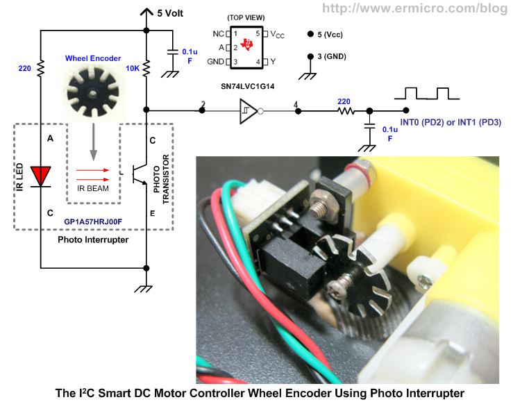
When the wheel rotate it will generate a pulse according to the wheel encoder disc pattern, which block and un-block the infrared (IR) beam emitted to the photo transistor. The photo transistor will be turn ON and OFF and the output is feed into the Schmitt trigger inverter SN74LVC1G14 to make the pulse transition smoother. By using the ATmega168 AVR external interrupt request INT0 (PD2) for left wheel encoder and INT1 (PD3) for right wheel encoder, we could easily count the pulse generated by the wheel encoder.
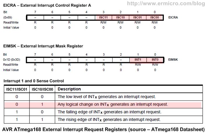
The AVR ATmega168 microcontroller external interrupt request is controlled by EICRA (External Interrupt Control Register A) and EIMSK (External Interrupt Mask Register). To achieve maximum resolution from the encoder disc which has 20 PPR (Pulse per Rotation) resolution, we set the ISC11 and ISC10 bits to logical “0” and the ISC01 and ISC00 bits to logical “1”. This setting will generate interrupt every time the input logical change i.e. low to high or vice verse.
The external interrupt request INT0 and INT1 is initialized in the main() function as shown on this following C code:
// Set EICRA Register on ATmega168
// ISC01=0; ISC00=1;
// ISC11=0; ISC10=1;
// Enable External Interrupt INT1 and INT0 at Any Logical Change
EICRA = (1<<ISC10)|(1<<ISC00);
EIMSK = 0b00000000; // Disable Interrupt INT0 and INT1
The external interrupt request INT0 or INT1 is activate in the MotorDuration() function, where this function will examine the motor_contl variable and activate it accordingly by enabling either INT0 or INT1 bit in EIMSK register:
if ((motor_contl & 0x40)) {
  EIMSK = (1<<INT1);    // Enable External Interrupt INT1
} else {
  EIMSK =(1<<INT0);     // Enable External Interrupt INT0
}
In this implementation of the I2C smart motor controller we only activate one external interrupt request at the time as we only want to control the rotation and degree on one particular wheel at the time. Next the actual wheel encoder pulse count is implemented in ISR(INT0_vect) and ISR(INT1_vect) function.
For timing based control wheel rotation I simply use the AVR ATmega168 microcontroller 8-bit Timer/Counter0 (TIMER0) peripheral, configured in compare match mode to generated compare match interrupt every 10 ms which serve as the basic timing for wheel rotation duration measured in seconds (1 to 255). The TIMER0 compare match is initialized inside main() function as shown in this following C code:
// Time Based Motor Control Initialization using TIMER0
// TCNT0 Counter Increment Period = 1 / (Fclk/1024)
//                         Period = 1 / (16000000/1024) = 0.000064 Second
TCCR0B=(1<<CS02)|(1<<CS00);  // Start TIMER0, use Maximum prescaler: 1024
TCNT0=0;                     // Start counter from 0
OCR0A=157;                   // Interrupt Every 157 x 0.000064 = 0.010048 Second (10 ms)
TIFR0=(1<<OCF0A);            // Clear any pending TIMER0 Compare A Interrupt
TIMSK0 &= ~(1<<OCIE0A);      // Disable TIMER0 Compare A Interrupt
Next the 1 second timing is implemented in ISR(TIMER0_COMPA_vect) function where the count_dur variable will be compared to the motor_dur variable in order to determine the wheel rotation timing. You could get more information about TIMER0 peripheral on the Working with AVR microcontroller Communication Port Project article.
Controlling the Servo Motor
The I2C Smart Motor Controller is also equipped with one servo motor control port implemented on AVR ATmega168 microcontroller I/O PB0 (PORTB). Basically servo motor used PWM for controlling the motor direction or position. Most of servo motor will work well on 50 Hz of PWM frequency; this mean the PWM signal should have a period of 20 ms (i.e. Period = 1 / Frequency = 1 /50 = 0.02 second). The electronic circuit inside the standard servo motor will response to the PWM signal width range from 0.7 ms to 2 ms as shown in this following picture:
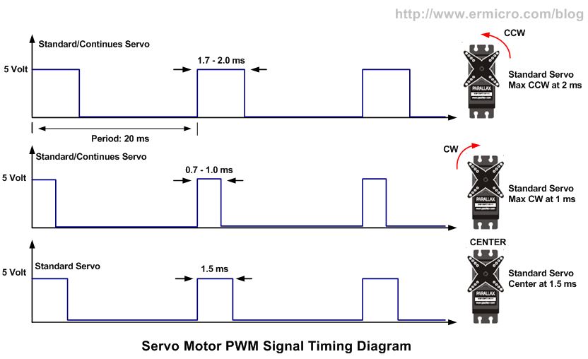
Therefore by controlling the PWM width timing we could easily move the servo arm at the precise position. For example to move clock wise (CW) slightly from center we could supply a pulse width of 1.6 ms or to move counter clock wise (CCW) slightly from maximum CW we could supply a pulse width of 1.1 ms. Therefore by increasing the pulse width from 1.0 ms to 2.0 ms we could move the servo’s arm smoothly from maximum CW to maximum CCW or by decreasing the pulse width from 2 ms to 1 ms we could move the servo’s arm from maximum CCW to maximum CW.
To generate the PWM suitable for the servo I used the AVR ATmega168 microcontroller 8-bit Timer/Counter2 (TIMER2) peripheral in compare match mode. The TIMER2 compare match interrupt will be serve as the basic timing of 0.01 ms for the servo PWM signal as shown on this following C code inside the main() function:
// Time Based Servo Control Initialization using TIMER2
// TCNT2 Counter Increment Period = 1 / (Fclk/8)
//                         Period = 1 / (16000000/8) = 0.0000005 Second
TCCR2B=(1<<CS21);            // Start TIMER2, use prescaler of 8
TCNT2=0;                     // Start counter from 0
OCR2A=20;                    // Interrupt Every 20 x 0.0000005 = 0.00001 Second (0.01 ms)
TIFR2=(1<<OCF2A);            // Clear any pending TIMER2 Compare A Interrupt
TIMSK2 &= ~(1<<OCIE2A);      // Disable TIMER2 Compare A Interrupt
The servo_period variable inside ISR(TIMER2_COMPA_vect) function is used as a counter which keep the servo PWM period length of 20 ms. When it reach the maximum value of 2000 (MAX_VALUE), then the PB0 of PORTB will be turned ON. Next the servo_on variable will start to increase and it is used as a counter to control the pulse width period, when the servo_on value reach the servo_pos variable value then the PB0 will be turned OFF. The following servo motor PWM timing diagram will show you clearly of how it works.
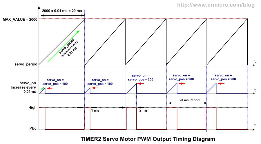
By assigning the servo_pos variable with the value of 100 to 200 (i.e. 1 ms to 2 ms), we could move the servo motor arm to the desired position. Because most of the standard servo motor arm could move up to 110 degree, therefore using this method you could move the servo arm at 1.1 degree resolution. The I2C Smart Motor Control servo position inside the ControlAction() function limit the value between 100 to 200, but you could experiment to stretch this value by changing the C code inside this function, say from 80 to 220 (i.e. 0.8 ms to 2.2 ms) to increase the servo angle:
…
case SMPOS:
   if (rw_status) {
     if (regdata >= 220) {
    smotor_pos = 220;    // Maximum Servo Motor Position: 200 x 0.01ms = 20ms
     } else {
      smotor_pos=80 + regdata; // Write To Servo Motor Position register
     }

     TCNT2=0;               // Start counter at 0
     TIFR2=(1<<OCF2A);      // Clear any pending TIMER2 Compare A Interrupt
     servo_period=0;        // Reset Servo Period Count
     servo_on=0;            // Reset Servo On Period Count
     servo_pos=smotor_pos;  // Assigned Servo Position
   } else {
     regdata=smotor_pos - 80;  // Read from Servo Motor Position Data register
   }
   break;
…
The Analog Sensor Reading
Beside motor control, the I2C Smart Motor Controller is also equipped with one 10-bit analog port to read analog input or sensor and return the value range from 0 to 1023. The analog is implemented using AVR ATmega168 10-bit ADC peripheral. You could read more about the AVR ATmega168 ADC peripheral in the Analog to Digital Converter AVR C Programming articles. The ADC peripheral is initialized inside the main() function using ADC channel 3 on PORTC (PC3) as shown in this following C code:
// Set ADCSRA Register on ATmega168
// ADEN=0 - Disable the ADC Peripheral
// ADPS2=1, ADPS1=1, and ADPS0=1 we used prescale of 128
ADCSRA = (1<<ADPS2) | (1<<ADPS1) | (1<<ADPS0);
ADCSRB = 0b00000000;          // Free Running Mode
DIDR0  = 0b00001000;          // Use analog input for Channel 3

// Set ADMUX Register on ATmega168
// Use AVcc Voltage Reference, Right, and select the ADC channel 3 (ADC3 - PC3)
ADMUX = 0b01000011;
When the ADC feature is enable then the ADC input reading will take place inside the while(1) infinite loop which return the lower 8-bit value in adc_low variable and the high 2-bit value in adc_high variable.
The I2C Smart Motor Controller Protocol
As described in part 1, in order to communicate efficiently with this I2C Smart Motor Controller, We used a protocol where we treat the I2C Smart Motor Controller board as the I2C slave device which has several 8-bit control registers. Each of these registers will implement one or more functions. Therefore by simply writing to or reading from these registers we could easily control this board.
For example let’s say we want to move forward the motor and make arching slightly to the right for about 10 rotation at the power of 70%, all we have to do is to assign the correct value to the I2C Smart Motor Controller 8-bit control register as shown in this following C language like pseudo code:
MPOWER = 70;          // Set PWM to 70%
MDURA = 10;           // Set Duration for 10
MSTEER = 110;         // Arching to the Right, default center at 100
MCONTL = 0b00010001;  // Move: Forward, Duration: Rotation, Used left Wheel Encoder
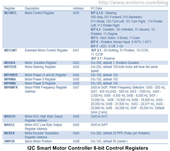
When the last statement is executed, both the left and right motor will start to move with 70% of speed, with the MSTEER register is assigned to 110, the right motor will get less power compared to the left motor, therefore it will move forward slightly to the right. The motor steering is implemented in MotorSteering() function. By setting the bit 4 and 3 in MCONTL register we could select the duration (e.g. rotation) and the length of duration is determined by the value assigned to MDURA register (e.g. 10 rotation). The following is a complete list of the I2C Smart Motor Controller 8-bit control registers.
The following is example is a C language like pseudo code to move the servo about 11 degree CCW and reading the analog input while moving both the motor forward at 65% with unlimited duration:
unsigned int analog_read;
unsigned char adc_high, adc_low;

MPOWER = 65;          // Set PWM to 65%
MCONTL = 0b10000001;  // Move: Forward, Duration: Unlimited, ADC On
MECONT = 0b00000001;  // Prepare the Servo for Position
SMPOS = 60;           // Move servo about 11 degree CCW from center (center 50)
adc_high = MADCH      // Read the High ADC 2-bit value
adc_low = MADCL       // Read the Low ADC 8-bit value

// Get the 10-bit ADC Value
analog_read = adc_low + (adc_high << 8);
As you notice, because the ADC value is stored in MADCH and MADCL registers, therefore in order to get the 10-bit ADC result we need to combine these values as we assign them to the analog_read variable.
The Master Controller Board
When prototyping the I2C Smart Motor Controller board (AVR ATmega168 microcontroller), I used similar microcontroller family i.e. AVR ATmega328 microcontroller as the I2C master controller, so I don’t have to change the IDE (Integrated Development Environment) and programmer when testing all the I2C Smart Controller board features. And because both microcontroller have similar I2C peripheral, therefore debugging the program become fast and easier.
Once it work, we could change the I2C master controller to a different microcontroller brand. In this article I used Microchip 8-bit 20 pin PIC16F1829 microcontroller, which has a different I2C peripheral and programming environment compared to the Atmel AVR microcontroller families.
Remote UART Serial Communication
UART (Universal Asynchronous Receiver Transmitter) is one of popular method widely used in embedded word to communicate serially with other devices. Therefore today there are many kind of wireless UART/TTL (Transistor-transistor Logic) interface module available on the market. The terms TTL means the UART module is designed to interface with standard TTL logical voltage level (i.e. 0 to 5 volt) instead of RS232 signal voltage level specification (i.e. +/- 3 volt or +/- 12 volt).
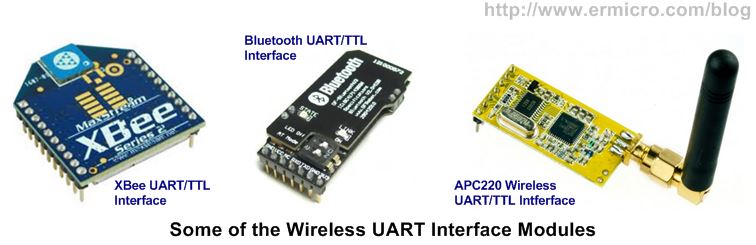
In this project I used the Bluetooth UART/TTL for practical reason as most of laptop or Smartphone has already equipped with the Bluetooth peripheral, therefore to establish a serial Bluetooth communication with all of these devices is easier. The only drawback of using Bluetooth device is the radio transmitter range is limited, in my case is about 10 meters line of sight. Mean while the APC220 Wireless UART/TTL shown above have a range for about 1000 meters, but you need to have a pair of it in order to be able to setup a serial radio link.
To control our robot remotely through the wireless UART serial communication, we need to create a simple command line that will be entered from the serial terminal program such as TeraTerm or Putty on MS Window platform, or you could use the Bluetooth Terminal program on Android platform (I used SENA BTerm application). This command line than will be interpreted by the I2C master controller and pass the command to the I2C Smart Motor Controller board.
The Bluetooth module will be act as a slave Bluetooth device that connect to the PIC16F1829 microcontroller through the EUSART (Enhanced Universal Synchronous Asynchronous Receiver Transmitter) peripheral with a standard 9600 baud rate and 8-bit data.
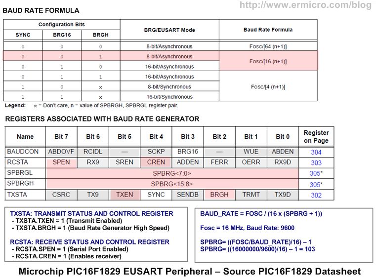
The EUSART is initialized in uart_init() function, where the desired baud rate could be calculated using this following formula:
BAUD_RATE = FOSC / (16 x (SPBRGH:SPBGRL + 1))
Using the PIC16F1829 microcontroller 16 MHz internal oscillator and 9600 baud rate, we could calculate the value of the register SPBRGH (high byte) and SPBRGL (low byte) as follow:
SPBRGH:SPBGRL = ((FOSC/BAUD_RATE) / 16) – 1
SPBRGH:SPBGRL = ((16000000/9600) / 16) – 1 = 103
The complete C code for setting the PIC16F1829 microcontroller EUSART peripheral in Asynchronous mode is shown in this following C code:
unsigned int BRGValue;

TRISBbits.TRISB5 = 1; // Set Port RB5 for UART RX (Input)
TRISBbits.TRISB7 = 1; // Set Port RB7 for UART TX (Output)

// Baud Rate formula for SYNC=0 (Async), BRG16=0 (8-bit), BRGH=1 (High Speed)
// 0.16% Error for 16 MHz Oscillator Clock. Actual Rate will be 9620.
// BAUD_RATE = FOSC / (16 x (SPBRGH:SPBGRL + 1))
BRGValue=(unsigned int) ((FOSC/BAUD_RATE)/16) - 1;
SPBRGH=(BRGValue >> 8) & 0x00FF;
SPBRGL=BRGValue;

TXSTA = 0b00100100;  // Async, 8 bit, High Speed (BRGH=1), and Enable Transmit (TXEN=1)
RCSTA = 0b10010000;  // Serial Port Enable (SPEN=1), Async,8-bit and Enable Receipt (CREN=1)
BAUDCON=0b00000000;
Next the Bluetooth Master on the PC (personal computer) will establish the connection with the Bluetooth slave using the Bluetooth Serial Port Protocol (SPP) service (e.g. COM18 in my computer) as shown in this following picture:
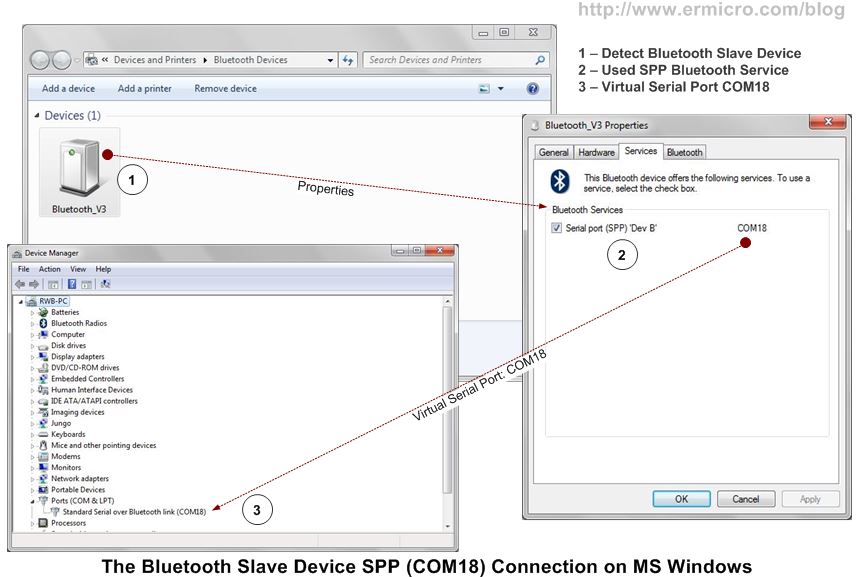
Therefore by setting the TeraTerm application serial port on COM18 with 9600 baud rate, we could establish a wireless serial communication with the PIC16F1829 Microcontroller EUSART peripheral which act as the master controller to the I2C Smart Motor Controller board as shown in this following picture:
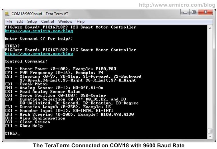
The command line as shown on the above picture is implemented inside the main() function, where it is designed to use a single letter followed by number to control various I2C Smart Motor Controller board features. To demonstrate how we use this command line, I will use similar example as described above where we want to move forward the motor and make arching slightly to the right for about 10 rotation at the power of 70:
CTRL>P70  // Set PWM to 70%
CTRL>D2   // Select Wheel Duration using Wheel Rotation
CTRL>L10  // Set Duration Length for 10
CTRL>E0   // Used INT0 as the Encoder Input
CTRL>A110 // Arching to the Right, default center at 100
CTRL>S1   // Move Forward
As you could see from the example above, although this command line looks odd, but this a simple and neat solution to communicate with a serial enabled device. The command line protocol principle that I used here could be traced way back in the days when most of the legacy system mainly used the RS232 to communicate with different dumb terminals types and brand such as Wyse 60 or DEC VT100. Each type of this dumb terminal need to be controlled by a special command protocol which usually a combination of ASCII characters and numbers. Nowadays you still could found this obsolete protocol in the /etc/termcap file on major Linux operating system distribution.
Once we determined and tested all the necessary commands line to control the telepresence robot, it would be easy to develop a graphics user interface (GUI) application that will encapsulate all the commands and communicate directly to the telepresence robot through a serial communication protocol.
Therefore in order to make operating this teleprensence robot fun and enjoyable, I build a simple MS-Windows based application named “I2C BlueTooth Control” using MS Visual Basic 2012 that transform all the commands line into a nice GUI button or slider and connect the serial communication directly to the Bluetooth device as shown in this following picture .

The PIC16F1829 Microcontroller I2C Peripheral
The Microchip PIC16F1829 microcontroller I2C peripheral is the part of Master Synchronous Serial Port (MSSP) peripheral and there are two MSSP peripherals (MSSP1 and MSSP2) in PIC16F1829 microcontroller. Each module could be operated in one of the two modes: Serial Peripheral Interface (SPI) or Inter-Integrated Circuit (I2C). The I2C module support both I2C master and I2C slave modes, where in this project we will use the I2C Master mode on MSSP1. You could read more about using the Microchip MSSP peripheral in Interfacing the Microchip PIC18 Microcontroller Master Synchronous Serial Port (MSSP) Peripheral to various I2C Devices article in this blog.
The MSSP1 I2C master peripheral is initialized in i2c_init() function where we set the I2C master clock speed at standard 100 kHz using this following formula:
I2C Master Clock Speed = FOSC/(4 * (SSP1ADD + 1))
Using the internal clock speed of 16 MHz and by assigning the MSSP1 Address and Baud Register (SSP1ADD) with 39 we will get this following result:
I2C Master Clock Speed = 16000000/(4 * (39 + 1)) = 100000 Hz = 100 kHz
The following list show all the MSSP1 functions used in this program:
- I2C_init() – initialized the PIC16F1829 MSSP1 peripheral in I2C master mode at 100 kHz.
- i2c_idle() – Wait for I2C bus idle status
- i2c_start() – Insert I2C master start condition on the I2C bus
- i2c_stop () – Insert I2C master stop condition on the I2C bus
- i2c_slave_ack () – Examine the I2C slave acknowledge status
- i2c_write() – Write data to the I2C bus
- i2c_master_ack() – Insert I2C master acknowledge on the I2C bus
- i2c_read() – Read data from the I2C bus
- Write_I2CMCTL() – I2C write wrapper to the I2C Smart Motor Controller
- Read_I2CMCTL() – I2C read wrapper from the I2C Smart Motor Controller
Now you could watch and enjoy the entire project presented here on this following video, where you could see how this telepresence robot in action.
The Final Though
In this project we’ve learned to use a different microcontroller brand (i.e. Atmel AVR ATmega168 microcontroller and Microchip PIC16F1829 microcontroller) to achieve our goal, even though most of the embedded system designers tend to use a similar microcontroller family in their design in order to reduce cost in production. It is a good practice to every embedded system designers not to be “locked” in the particular microcontroller type, but keep open their mind to the other microcontroller type or brand in order to broaden their knowledge. In the final part project (Part 3), I will use different microcontroller board as the I2C master controller to control this I2C Smart DC Motor Controller.
Bookmarks and Share


Comment by whitepaper.
Wow that was awesome. I have always enjoyed your avr/pic projects. I have gained a lot from this post.
Keep it up. I look forward to the next.
Rich