Blog Entry
Build Your Own Simple and Easy PICAXE Microcontroller Based Photovore Robot
February 4, 2010 by rwb, under Robotics.
Building a simple and easy microcontroller based robot is always a fascinating topic to be discussed, especially for the robotics newbie enthusiast. On this tutorial I will show you how to build your own microcontroller based robot which known as a photovore or you could call it as the light chaser robot using the simplest possible circuit for the microcontroller based robot brain, locomotion motor and the sensor.
One of the most frustrating parts when building your first microcontroller based robot is to program it and to download it into the microcontroller flash ram. On this tutorial this kind of “trouble maker” is being reduced as we will use the PICAXE programming editor from the Revolution Education Ltd (http://www.rev-ed.co.uk/picaxe) as our Integrated Development Environment (IDE) to program our robot brain using the BASIC (Beginners All Purpose Symbolic Instruction Code) language and to download the program into the PICAXE 28X1 microcontroller.
The PICAXE 28X1 microcontrollers actually is based on the popular Microchip 8-bit 28 pins PIC16F886 microcontroller that have a preload PICAXE BASIC interpreter firmware inside, in fact when you buy it its looks the same as the usual Microchip PIC16F886 microcontroller. Together with the free PICAXE Programming Editor and simple serial cable connector for the program downloader makes this PICAXE framework suitable for beginners and even for the professional.
You could read more information about the PICAXE microcontroller on my previous posted blog “Introduction to the Embedded system with PICAXE Microcontroller“.
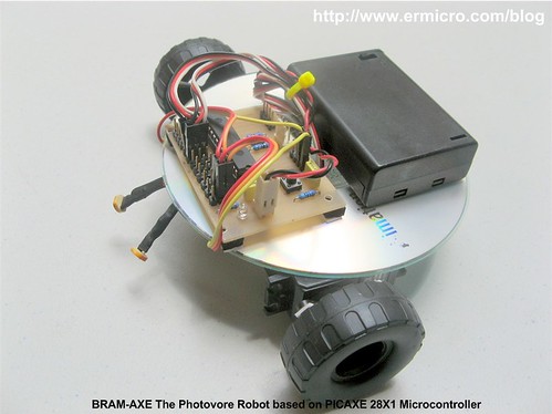
On this tutorial I will refer this photovore robot as the BRAM-AXE as this is a simplify version of the more advanced version of its big brother BRAM (Beginners Robot Autonomous Mobile) which you could read more information about it on my previous posted blog “Building BRAM your first Autonomous Mobile Robot using Microchip PIC Microcontroller – Part 1” and “Behavior Based Artificial Intelligent Mobile Robot with Sharp GP2D120 Distance Measuring Sensor – BRAM Part 2“.
The BRAM-AXE robot simply use its light sensitive sensor to navigate to the light source, when it being placed in the dark environment it will automatically switch to the light search mode and try to find the light source, when it encounter the light source it will navigate to the light source and when the light source intensity is bright enough it will stop and enjoying the light. You could see all this behavior on the video at the end of this tutorial. Ok now let’s list down all the electronics parts, robot chassis materials and software needed to build this interesting robot.

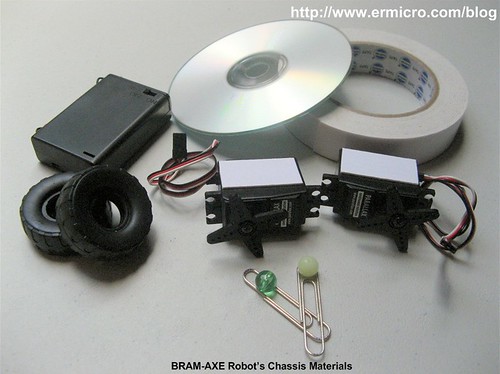
- BRAM-AXE board: based on the PICAXE 28X1 microcontrollers together with the PICAXE serial downloader cable which you could easily build from my previous posted blog “Make your own Microcontroller Printed Circuit Board (PCB) using the Toner Transfer Method“.
- Two LDR and Two 1K Ohm 0.25 watt resistor
- Two Continues Servo (on this tutorial I use the Parallax Continues Servo)
- Two toys tire to be attached to the servo’s arms
- Enough cables and Tubing (1mm and 3mm)
- 3 x AA battery holder with 3 x AA alkaline battery
- 1 CD or DVD
- A good double tape or epoxy glue for the permanent robot
- One paper clips and neck less beads for the robot caster (the robot’s third wheel)
- Enough bolts and nuts for the caster
- PICAXE Programming Editor from Revolution Education Ltd which you could download from their website
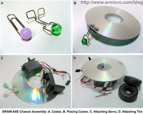
The BRAM-AXE Chassis Assembly
The BRAM-AXE main chassis is made from the CD/DVD which you could find easily at home or just use the blank one as I did if you don’t have any discarding CD/DVD at home. For the wheel you could use any toy’s wheel or you could use anything that has a circle form as long as the diameter is greater or equal to the servo’s arms.
The assembly of BRAM-AXE chassis is straight forward; you just need to drill two holes for placing the caster. Attached the two continues servo on the button of the CD/DVD with the double tapes and attached the wheel to the servo’s arms with the double tape or you could use the epoxy for permanent one. You could see the whole process on these following pictures:
Now attached the 3 x AA battery holder and BRAM-AXE board on top of the CD; again using our flexible friend the double tape as shown on these following pictures.

Connect the power socket to the BRAM-AXE polarized power pin and the servo’s socket to the BRAM-AXE board output 0 and output 1 three pins socket respectively as shown on this following servo’s circuit diagram.

The BRAM-AXE board output pins is design to be attached directly with the servo, every output pins provide both power and ground needed to power the servo. Connect the left servo connector to the BRAM-AXE output 0 and the right servo connector to the BRAM-AXE output 1. After finishing all this steps now it’s the time to test the robot steering mechanism.
The BRAM-AXE Steering Method
The BRAM-AXE steering use the simple method called the “differential drive“; when the two servos rotate on the same direction the robot will move forward or backward, and when they rotate on different direction (counter rotation to each other) the robot will rotate to left or right.
Servo basically is a high quality geared DC motor with electronic circuit for controlling the DC motor rotation direction and position; its being used widely in model hobbyist such as car R/C model for steering and acceleration control or airplane R/C model for moving the rudder, ailerons, elevators and acceleration control. Typically there are two type of servo available on the market the first one is “standard” servo which could rotate between 120 to 180 degree and the second one is “continues” servo which could rotate 360 degree.

By using the continues servo, the locomotion circuit become very simple as we only connect the servo directly to the BRAM-AXE board and supply the correct PWM (Pulse Width Modulation) signal in order to make it rotate. The PICAXE BASIC language has a build in servo commands that we could use to make the servo rotate.
servo output_pin, n
servopos output_pin, n
The servo command will initial the PICAXE 28X1 (Microchip PIC16F886) internal TIMER which is used to generate the PWM signal to the servo and after initialization you have to use the servopos command in order to control the servo. The n is the number between 75 and 255, where this number will determine the servo rotation direction (clock wise or counter clock wise). The output_pin is the PICAXE 28X1 output pin which range from 0 to 7.
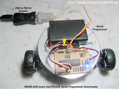
Now connect the serial programming cable from the BRAM-AXE board to your computer COM/RS232 port or you could use the USB to RS232 adapter as I did and download this following servo testing program using the PICAXE Programming Editor:
'***************************************************************************
'  File Name    : bram-axe_servo_test.bas
'  Version      : 1.0
'  Description  : BRAM-AXE Photovore Servo Testing
'  Author       : RWB
'  Target       : BRAM-AXE Learning Board - PICAXE 28x1
'  Intepreter   : PICAXE Firmware version A.6
'  IDE          : PICAXE Programming Editor Version 5.2.6
'  Programmer   : PICAXE Programming Editor Version 5.2.6
'  Last Updated : 03 January 2010
'***************************************************************************
' Use PICAXE 28x1 with 4 MHz Internal Clock
#picaxe 28x1
SetFreq m4
' Assigned Variables
symbol cnt_val = b0
symbol move_mode = b1
let pins = %00000000 ' Reset all the Output Pins
' Initial the Servo
gosub BRAM_ServoInit
move_mode=1
cnt_val=1
main:
  select move_mode
    case 1
      gosub BRAM_MoveForward
    case 2
      gosub BRAM_MoveBackward
    case 3
      gosub BRAM_RotateRight
    case 4
      gosub BRAM_RotateLeft
    case 5
      gosub BRAM_Stop
    case 6
      gosub BRAM_ServoInit
  end select

  pause 10        ' Pause 10 Second
  cnt_val=cnt_val + 1
  if cnt_val > 150 then
    move_mode=move_mode + 1
    if move_mode > 6 then
      move_mode=1
    endif
    cnt_val=1
  endif

  goto main      ' Back to main loop
  end
' BRAM Steering Subroutines
BRAM_ServoInit:
  servo 0,125        ' Left Servo
  servo 1,200        ' Right Servo
return
BRAM_MoveForward:
  servopos 0,125     ' Left Servo Forward
  servopos 1,200     ' Right Servo Backward
return
BRAM_MoveBackward:
  servopos 0,200     ' Left Servo Backward
  servopos 1,125     ' Right Servo Forward
return
BRAM_RotateRight:
  servopos 0,125     ' Left Servo Forward
  servopos 1,125     ' Right Servo Forward
return
BRAM_RotateLeft:
  servopos 0,200     ' Left Servo Backward
  servopos 1,200     ' Right Servo Backward
return
BRAM_Stop:
  settimer off       ' TIMER Off
return
' EOF: bram-axe_servo_test.bas

Usually the servo is designed to have a wide tolerance on the incoming PWM signal, but if your servo doesn’t work with the above value (125 and 200) try to experiment with other value as long as the value range is between 75 and 255. For more information about controlling the servo you could read my previous posted blog “Basic Servo Motor Controlling with Microchip PIC Microcontroller“.
The BRAM-AXE Sensors
In order to make the complete photovore robot, we need to use the light sensitive sensor; the simple and cheapest one is to use a special made resistor (made from Cadmium Sulfide) called Light Dependent Resistor or LDR for short. The LDR will vary its resistance according to the light intensity fall on its surface; the bright light intensity will make its resistance decrease significantly (about 1K Ohm to 5 K Ohm) while on the completely dark its resistance will increase as high as 100 K Ohm.

By connecting the LDR in series with 1 K Ohm resistor, we could get the simplest possible light sensor circuit that will give us the variable voltage output according to the light intensity as shown on this following picture.

This simple circuit is known as the voltage divider circuit, you could read more information about the voltage divider circuit on my previous posted blog “Basic Resistor Circuit“.
Connect the sensor circuit output directly to the PICAXE 28X1 microcontroller analog to digital conversion (ADC) input port (ADC 0 and ADC 1) and use the power taken from the BRAM-AXE board output pin as shown on these following pictures:

With the PICAXE ADC feature, now we could easily read the numeric representation of the light intensity on each sensor (left LDR and right LDR) using this following PICAXE BASIC commands:
readadc adc_channel, variable
The readadc command will read the ADC input port (0 to 3 on PICAXE 28X1 microcontroller) and assigned the 8-bit data value to the variable. By examining the ADC value we could command our robot to follow the light as shown on this following BRAM-AXE_photovore.bas program:
'***************************************************************************
'  File Name    : bram-axe_photovore.bas
'  Version      : 1.0
'  Description  : BRAM-AXE Photovore
'  Author       : RWB
'  Target       : BRAM-AXE Learning Board - PICAXE 28x1
'  Intepreter   : PICAXE Firmware version A.6
'  IDE          : PICAXE Programming Editor Version 5.2.6
'  Programmer   : PICAXE Programming Editor Version 5.2.6
'  Last Updated : 03 January 2010
'***************************************************************************
' Use PICAXE 28x1 with 4 Mhz Internal Clock
#picaxe 28x1
SetFreq m4
' Assigned Variable
symbol ldr_left = b0
symbol ldr_right = b1
symbol diff_value = b2
symbol mode = b3
symbol cnt = b4
symbol stop_stat = b5
let pins = %00000000 ' Reset all Output Pins
' Initial variable used
mode=0
cnt=0
stop_stat=0
main:
  ' Read the LDR ADC Value
  readadc 0,ldr_left
  readadc 1,ldr_right
  ' For Debugging the ADC Value
  ' sertxd("LDR Left: ",#ldr_left,13,10)
  ' sertxd("LDR Right: ",#ldr_right,13,10)
  ' pause 100

  ' Searching Mode if both LDR less or equal to 5
  if ldr_left <= 5 and ldr_right <= 5 then
    cnt=cnt + 1
    if cnt > 80 then
      cnt=0
      mode=mode + 1
      if mode > 5 then
        mode = 0
      endif
    endif

    select mode
      case 1
        gosub BRAM_Stop
      case 2
        gosub BRAM_RotateRight
      case 3
        gosub BRAM_MoveBackward
      case 4
        gosub BRAM_RotateLeft
      case 5
        gosub BRAM_MoveForward
    end select

    pause 10
    goto main
  endif
  ' STOP both LDR greater or equal to 90
  if ldr_left >= 90 and ldr_right >= 90 then
    gosub BRAM_Stop
    pause 10
    goto main
  endif

  ' BRAM-AXE Bang-Bang steer control
  if ldr_left > ldr_right then
    diffvalue=ldr_left - ldr_right
    if diff_value >= 20 then
      gosub BRAM_RotateRight
    else
      gosub BRAM_MoveForward
    endif
  endif

  if ldr_right > ldr_left then
    diffvalue=ldr_right - ldr_left
    if diff_value >= 20 then
      gosub BRAM_RotateLeft
    else
      gosub BRAM_MoveForward
    endif
  endif

  pause 10       ' Pause 10 seconds

  goto main      ' Back to main loop
  end
' BRAM Steering Subroutines
BRAM_MoveForward:
  if stop_stat = 1 then
    servo 0,125        ' Init Left Servo Forward
    servo 1,200        ' Init Right Servo Backward
    stop_stat=0
  else
    servopos 0,125     ' Left Servo Forward
    servopos 1,200     ' Right Servo Backward
  endif
return
BRAM_MoveBackward:
  if stop_stat = 1 then
    servo 0,200        ' Init Left Servo Backward
    servo 1,125        ' Init Right Servo Forward
    stop_stat=0
  else
    servopos 0,200     ' Left Servo Backward
    servopos 1,125     ' Right Servo Forward
  endif
return
BRAM_RotateRight:
  if stop_stat = 1 then
    servo 0,125        ' Init Left Servo Forward
    servo 1,125        ' Init Right Servo Forward
    stop_stat=0
  else
    servopos 0,125     ' Left Servo Forward
    servopos 1,125     ' Right Servo Forward
  endif
return
BRAM_RotateLeft:
  if stop_stat = 1 then
    servo 0,200        ' Init Left Servo Backward
    servo 1,200        ' Init Right Servo Backward
    stop_stat=0
  else
    servopos 0,200     ' Left Servo Backward
    servopos 1,200     ' Right Servo Backward
  endif
return
BRAM_Stop:
  stop_stat=1
  settimer off
return
' EOF: bram-axe_photovore.bas
The key for this photovore program to work properly is to place the two LDR sensors about 45 degree from the center of the robot chassis as shown on these following pictures:

When the two LDR sensors get an equal light intensity than we command the BRAM-AXE to move forward, when the light intensity is bright enough than we make it stop as shown on this PICAXE BASIC code:
' STOP both LDR greater or equal to 90
if ldr_left >= 90 and ldr_right >= 90 then
  gosub BRAM_Stop
  pause 10
  goto main
endif
When one of the LDR sensors is brighter then the other than we command the BRAM-AXE to rotate right or rotate left:
' BRAM-AXE Bang-Bang steer control
if ldr_left > ldr_right then
    diffvalue=ldr_left - ldr_right
    if diff_value >= 20 then
      gosub BRAM_RotateRight
    else
      gosub BRAM_MoveForward
    endif
endif

if ldr_right > ldr_left then
    diffvalue=ldr_right - ldr_left
    if diff_value >= 20 then
      gosub BRAM_RotateLeft
    else
      gosub BRAM_MoveForward
    endif
endif
When both LDR sensors is quite dark than we command the BRAM-AXE to enter the light search mode, this light search program algorithm will keep the BRAM-AXE to move forward, backward, rotate left and right until it locate the light source.
The BRAM-AXE photovore program algorithm use the simplest steering method control called the bang-bang control or on/off control which is the simplest closed loops control method usually used in the embedded system. For more information about the bang-bang control method you could read my previous posted blog “Basic Servo Motor Controlling with Microchip PIC Microcontroller“.
You could adjust all the bang-bang control numeric values to suite your need, in order to do that you have to know the ADC value before making your adjustment. This could be done by opening the commented PICAXE BASIC serial data transmit and pause command on these following lines:
' For Debugging the ADC Value
sertxd("LDR Left: ",#ldr_left,13,10)
sertxd("LDR Right: ",#ldr_right,13,10)
pause 100
You could display these value directly to the PICAXE Programming Editor build in serial terminal, which you could access from menu PICAXE -> Terminal or you could press the F8 key, re-down load the code again to run this monitor. Do not disconnect the serial programmer cable from the BRAM-AXE board as the PICAXE BASIC sertxd command use this serial connection to transmit the data and make sure you set the baud rate to 4800 as shown on this following picture:

Now as you have completely build your own photovore robot its time to watch this cute and simple robot in action:
The Final Though
As you’ve learned to build this simple and easy to build photovore robot hopefully this will trigger your passion to learn more about robotics and the embedded system. Learning by experiences is the key to success in learning the embedded system, keep experimenting as this will build your understanding and confidence in developing your own embedded system project.
Bookmarks and Share


Related Posts
31 Responses to “Build Your Own Simple and Easy PICAXE Microcontroller Based Photovore Robot”
Comment by rwb.
The thumb or fingerprint reader usually use the DSP (digital signal processor) class microcontroller for processing the image. If you want to start work with the fingerprint project; my suggestion is to use the ready made fingerprint module available on the market which give you the image read, store and search capabilities. Usually this module will communicate through RS232 or SPI.
Comment by wangui_esther.
Unfortunately, am not familiar with the DSP. You say its a separate class of microcontrollers. Can you give me an example? Also what if the computer is very far will an RS232 still be used for communication? I want it so it operates like an ATM. as long as your details are in a database somewhere you can log in from anywhere. Thanks
Comment by rwb.
For the finger print image processing there are already available module in the market, although building this type of module from scratch is possible but definitely need more skill and time. Ok, it seem to me that you want to build something similar to the time attendance machine and because this topic is not related anymore within this post, therefore I will email you directly my comment.
Comment by duke0817.
hey, awesome robot, just one question, how would i go around using this code, but to manipulate so i could use it as a line following robot, IE, following a black line on a white background and vice versa
Comment by rwb.
You need to illuminate the LDR with the light source (e.g. LED) and change the logic for steering the robot. You could read more about LFR principal on “Build Your Own Transistor Based Mobile Line Follower Robot (LFR) First Part” and “The LM324 Quad Op-Amp Line Follower Robot with Pulse Width Modulation” articles ini this blog
Comment by unni.0p.
can i make wall avioding robot with this pcboard?
or any other robots
Comment by unni.0p.
can i connect Sharp Analogue InfraRed Range Finding System (AERS)with this board
Comment by rwb.
Yes, in fact you could use this BRAM-AXE board (PICAXE 28X1) for any robotics project and connect the Sharp infrared range to one of its ADC input.
Comment by unni.0p.
Thank you rwb
Pl s help me
I want to make a robot in this site
part 3 and part 2 with this board
http://letsmakerobots.com/taxonomy/term/6721
where do the aers connect
Comment by unni.0p.
another doubt also i am novice in robotics bt vry interested can use normal geared small motors for servo
Comment by rwb.
If you want to use the geared small motors you need to use the motor driver. You could not connect the motor directly to the PICAXE 28×1 microcontroller output port. Unlike the BRAM-AXE board the original PICAXE 28×1 starter kit board is equipped with the L293D motor driver chip.
Comment by unni.0p.
sorry for disturbing u again
while i ordered for a servo motor the specifications given was the following
can i use it for this project?
* Torque: 2kg/cm at 4.8V
* Operating speed: 0.15sec/60 degree
* Dead bandwidth: 7us
is it easy to make servo cotinusly rotating
Comment by rwb.
There are two type of servo motor, standard and continues. The servo motor used in this project is the Parallax Continues Servo
Comment by Eric88.
To:rwb
may i know what is the assembler code use to run this robot? because base on the example code given above is C code..
Comment by rwb.
In this project I used PICAXE BASIC language not a C code and because it used the PICAXE microcontroller therefore you could not program it with C or Assembler code.
Comment by unni.0p.
I made this robot
thank u for ur post
I want ur help more what will be the difference in code if use this as line follower and an edge avoid er?
And one more thing my laptop has the port 9pin how can connect it with a laptop
Comment by rwb.
The code will be slightly different. Basically you need two black line sensor (LDR + LED) as shown on this following article:
The LM324 Quad Op-Amp Line Follower Robot with Pulse Width Modulation
Then connect the sensors output to the PICAXE analog input ports (similar to this articles). The following are the simple Line Follower Robot logic:
– Go Straight when both sensor on the white surface
– Turn Left when the right sensor on the black line
– Turn Right when the left sensor on the black line
For the edge avoider you could simply use a switch which constantly close (logical high) on the normal surface (pressed by the robot’s chassis), but when on the edge the switch arm will simply fall because of gravitation and the switch will open (logical low). Base on this logical information you could program the robot to avoid the edge.
The Laptop 9 pins connector usually is the COM (RS232 communication) port, which is male DB9 connector (check the BIOS or OS) for the COM device. You could use similar to BRAM-AXE COM/RS232 programmer cable to connect to your Laptop as shown on this following article:
Make your own Microcontroller Printed Circuit Board (PCB) using the Toner Transfer Method
Comment by unni.0p.
Hai
Does the code work in this board that used on original picaxe boards ?(in original board the code for dc motor rotation, would it work for a servo motor on this board ?)
How can i connect a pir on this board ? how many pins have a pir?
what will be its values?
Can I use for ldr ir ldr and for led a ir led for a line follower?
my new notebook have not 9 pin port, can connect this board with it?
Thank u
Comment by rwb.
The DC motor is different compared to the Servo Motor. Basically the servo Motor is a geared DC motor with special electronic circuit inside, therefore the code have to be changed.
The PIR (Passive Infrared) sensor circuit basically will give you logical “1” (ON) output when it detect the object or “0” (OFF) when no object is detected, therefore you could connect to any digital input port.
Yes you could use IR (infrared) instead of LDR for the line follower robot sensor.
You could buy the USB to RS232 converter for connecting this board to your notebook (I used it in this project, see the picture above).
Comment by Renhar.
Hello.
I have tryed making this robot this week, my only problem is when I try to download the program onto the microcontroller I get an error saying that there is an error with my COM port.
So I ended up testing my COM download cable to see if it works. Hooked up Rx to Tx and checked in the terminal to see if i receive what I send. That worked just fine.
I figured maybe this type of download cable might not work on my pc so I tryed making a new one using a MAX 232 like in the data sheet like in manual 3 page 44 (http://www.rev-ed.co.uk/docs/picaxe_manual3.pdf).
But I still get the same problem.
I have read somewhere that there might be a problem and the cable will not work if i do not have a 5Volts power supply so I ended up checking that as well and it is 5V.
I am simply out of ideea.
Any chance you might have an ideea about what’s going on?
Waiting for an answer, Thank you.
PS: Gonna make a post on PICAXE forums as well maybe someone might help. I hope you don’t mind that
Comment by Renhar.
nvm, managed to fix it.
Comment by unni.0p.
Hai Rwb I made the robot with a pir, it works thank u
pls help me making another project,a dcmotor or servo motor should be work after 5 or six days how can make or which ic should i use(this is to make a machine to control mosquito)
Comment by rwb.
Congratulate, basically controlling servo motor is easier (as shown on this article), while DC motor require more circuit (H-Bridge) to drive it. For more information about driving DC motor you could read the following article:
Building BRAM your first Autonomous Mobile Robot using Microchip PIC Microcontroller – Part 1
Anyway what you mean by mosquito
Comment by ananth.
hi, im from malaysia and im took light chaser robot as my final year project. can u pls upload me c-programing source code for this project..pls its very urgent..
Comment by ananth.
and also im not using picaxe ..im use pic16f886.
Comment by معاذ عميرة.
Hello
Can I get the full programming link or file ready???
Comment by معاذ عميرة.
I will start the implementation of this project from scratch Do I need information not found the explanation above?
Or is it that a full explanation and pieces and proven
Will I completed this project on my own from the beginning
Please help
Thank you
Comment by rwb.
Sure you can, all the information required is already explained in the articles (see the necessary link for additional information) and you could just copy/paste the PICAXE BASIC code from the article above.
Comment by معاذ عميرة.
Can I use controller 16f877a
Or to stay on the above-mentioned controlled
Because I know for controlling 16f877a more
Comment by rwb.
No, you could not use ordinary Microchip PIC Microcontroller (i.e. PIC16F877A) to program with PICAXE BASIC Integrated Development Tools (i.e. using PICAXE BASIC language), unless you plan to use other development language such as Microchip C or Assembler. See the article “Introduction to the Embedded system with PICAXE Microcontroller” in order to understand what is the PICAXE Microcontroller.

Comment by wangui_esther.
Hi rwb, its me again. Now i have been reading the blogs you suggested for using a transistor as a switch and am still working on that end.
I have another question. i have another project that i have been given to work on. There is to be a microcontroller that accepts input from two sources, a keypad and a thumb reader. Then the thumb print is compared aganist a database and if a match is found there is a output to a display in form of a message, so the controller also outputs a to a display.
I was thinking any microcontroller with an ADC capability should work. Am i right? Also it possibe that the microcontroller can comunicate with a system where the database is stored while its functioning?
I will really appreciate your help.