Blog Entry
Building your own Simple Laser Projector using the Microchip PIC12F683 Microcontroller
April 13, 2010 by rwb, under Microcontroller.
The 8 pins PIC12F683 microcontroller is one of the smallest members of the Microchip 8-bit microcontroller families but equipped with powerful peripherals such as ADC and PWM capabilities. This make this tiny microcontroller is suitable for controlling the DC motor speed. In order to demonstrate the PIC12F683 capabilities and to make this tutorial more attractive, I decided to use the PIC12F683 microcontroller to generate simple and yet fascinating laser light show from a cheap keychain laser pointer.
The basic of laser light shown in many entertainments club or park mostly use two method; the first one is to beam the laser shower on the spectators and the second one is to display the laser drawing pattern on the screen. On this tutorial we are going to build the laser projector that displays the spirograph pattern on the screen using the tiny Microchip PIC12F683 microcontroller.
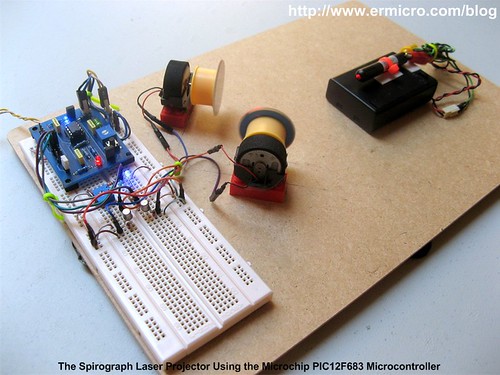
The principle of making the spirograph laser projector is to use at least two DC motors with the attached mirror on it, these mirrors then will deflect the laser beam from one DC motor mirror to the second DC motor mirror and then finally to the screen. By controlling each of the DC motors spinning speed we could generate a fascinating laser spirograph pattern on the screen as shown on this following picture.

The best way to control the DC motor speed is to use the PWM (pulse wave modulation) signal to drive the DC Motor and because we want to change the DC motor speed manually, therefore we need to use the trimport or potentiometer to control each of the DC motors speed. Hmm, this sound like an appropriate job for the microcontroller but could we use this tiny 8 pins PIC12F683 microcontroller to handle this task?

From the datasheet you will notice that the Microchip PIC12F683 microcontroller only has one PWM output (CCP1) and four ADC input channel (AN0, AN1, AN2 and AN3). Because we need two PWM output, therefore instead of using the PIC12F683 microcontroller build in PWM peripheral, in this tutorial I will show you how to generate the PWM signal base on the PIC12F683 microcontroller TIMER0 peripheral. The following is the complete electronic schematic for the laser projector project.

Ok before we go further with the detail; let’s list down the supporting peripherals needed to complete this laser projector project:
- Hot glue gun
- Keychain laser pointer or any available laser pointer
- 3xAA, 4.5 volt battery holder for powering the laser pointer, please use the same voltage rate used by your laser pointer.
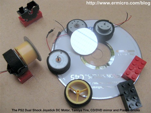
- Two DC motor taken from the discarded PS2 Dual shock joystick
- Two toy’s car tire taken from tamiya racing car
- CD/DVD for the mirror, use a kitchen scissor to cut the CD/DVD into the two circle shape mirror with approximately 38 mm in diameter
- Some toys plastic bricks for holding the DC motor
- Breadboard
- Hardboard or acrylic is used for the base of our laser projector
- Double Tape


The following are the electronic parts and the software development tools that I used to make this laser projector project:
- Resistor: 330 (3), 1K (5) and 10K (1)
- Trimport: 10K (2)
- Capacitor: 100nF (2) and 10nF (1)
- One 100uH Inductor
- Two 1N4148 Diodes
- Two Blue and one Red Light Emitting Diode (LED)
- Two 2N2222A transistors
- One Mini Push Button Switch
- One Microchip PIC12F683 Microcontroller
- Microchip MPLAB v8.46 IDE (Integrated Development Environment)
- Microchip Macro Assembler MPASMWIN.exe v5.35, mplink.exe v4.35
- HI-TECH C Compiler for PIC10/12/16 MCUs (Lite Mode) V9.70
- Microchip PICKit3 Programmer (Firmware Suite Version: 01.25.20)

This project is aim as the continuing lessons to my previous posted blog Introduction to PIC Assembly Language Part-1 and Introduction to PIC Assembly Language Part-2, therefore I used the same PIC12F683 board presented in the part 2 which you could down load both of the electronic schematic and the PCB layout designed in Eagle CAD format. The other interesting feature of this laser projector project is; besides the PIC assembly code I also provide the C language version of this project for the C language lover and is compiled with the HI-TECH C Compiler (recently the HI-TECH Software has been acquired by Microchip). This C language version could be used for learning as well as the embedded system programming language comparison.
In this project I also use a new Microchip PICKit3 programmer but of course you could use the Microchip PICKit2 programmer to download the hex code to the PIC12F683 microcontroller flash.
The following is the Laser Projector code in PIC Assembly Language:
;******************************************************************************
;  File Name    : laserlight.asm
;  Version      : 1.0
;  Description  : Laser Light Show Project
;  Author       : RWB
;  Target       : Microchip PIC12F683 Microcontroller
;  Compiler     : Microchip Assembler (MPASMWIN.exe v5.35, mplink.exe v4.35)
;  IDE          : Microchip MPLAB IDE v8.46
;  Programmer   : PICKit3 (Firmware Suite Version: 01.25.20)
;  Last Updated : 01 April 2010
; *****************************************************************************
#include <p12F683.inc>
__config (_INTRC_OSC_NOCLKOUT & _WDT_OFF & _PWRTE_OFF & _MCLRE_OFF & _CP_OFF & _IESO_OFF & _FCMEN_OFF)
#define MAX_TMR0 0xFB
#define MAX_COUNT .200
#define MAX_DEBOUNCE 0x0A
#define MAX_TBLINDEX 0x0A
; Define variables used
     cblock 0x20
Delay:2                      ; Define two registers for the Delay and Delay + 1
mode                         ; Operation Mode
pwm_count                    ; Hold the Main PWM Counter
pwm_m1                       ; Hold the PWM width for Motor 1
pwm_m2                       ; Hold the PWM width for Motor 2
keycount                     ; Debounce Count
tableindex                   ; Table Index for Auto PWM
     endc
; Define variable use for storing STATUS and WREG register
     cblock 0x70             ; Use unbanked RAM, available both in Bank0 and Bank1
saved_w
saved_status
     endc
; Start the Light show Assembler Code here
     org 0x00                ; We always start at flash address 0
     goto Main               ; Jump to Main
     org 0x04                ; 0x04: Start PIC Interrupt Address
PIC_ISR:                     ; Start the PIC Interrupt Service Routine
     movwf   saved_w         ; Save Working Register
     movf    STATUS,w        ; Save Status Register
     movwf   saved_status
; Check the TIMER0 Interrupt here
     btfss   INTCON,T0IF
     goto    ExitISR         ; If (T0IF != 1) then Exit ISR
     bcf     STATUS,RP0      ; Select Registers at Bank 0
     incf    pwm_count       ; pwm_count++
     movlw   MAX_COUNT
     subwf   pwm_count,w     ; if (pwm_count < MAX_COUNT) then CheckPWM
     btfss   STATUS,C        ; else clear GP1 and GP2
     goto    CheckPWM
     bcf     GPIO,GP1        ; GPIO1=0
     bcf     GPIO,GP2        ; GPIO2=0
     goto    ExitPWM
CheckPWM:
     movf    pwm_m1,w
     subwf   pwm_count,w
     btfsc   STATUS,Z        ; if (pwm_count == pwm_m1) then Set GP1
     bsf     GPIO,GP1        ; Set GP1 Bit
CheckM2:
     movf    pwm_m2,w
     subwf   pwm_count,w
     btfsc   STATUS,Z        ; if (pwm_count == pwm_m2) then Set GP2
     bsf     GPIO,GP2        ; Set GP2 bit
ExitPWM:
     bcf     INTCON,T0IF     ; clear the TIMER0 interrupt flag
     movlw   MAX_TMR0
     movwf   TMR0            ; TMR0 = MAX_TMR0
ExitISR:
     movf    saved_status,w
     movwf   STATUS          ; Restore STATUS Register
     swapf   saved_w,f
     swapf   saved_w,w       ; Restore W Register
     retfie                  ; Return from Interrupt
Main:
     bsf     STATUS,RP0      ; Select Registers at Bank 1
     movlw   0x70
     movwf   OSCCON          ; Set the internal clock speed to 8 MHz
     movlw   0x39            ; GP1 and GP2 Output, GP0,GP3,GP4 and GP5 as Input
     movwf   TRISIO          ; TRISIO = 0x39

     bcf     STATUS,RP0      ; Select Registers at Bank 0
     movlw   0x07
     movwf   CMCON0          ; Turn off Comparator (GP0, GP1, GP2)
     clrf    GPIO

; Now we Set the ADC Peripheral
     bsf     STATUS,RP0      ; Select Registers at Bank 1
     movlw   0x79            ; Set AN0 (GP0) and AN3 (GP4) as Analog Input
     movwf   ANSEL           ; Using the Internal Clock (FRC)

; Now we set the TIMER0 Peripheral
; TIMER0 Period = 1/FSOC x 4 x Prescale x TMR0
     movlw   0x00            ; Use TIMER0 Prescaler 1:2, Internal Clock
     movwf   OPTION_REG      ; OPTION_REG = 0x00
     bcf     STATUS,RP0      ; Select Registers at Bank 0
     movlw   MAX_TMR0
     movwf   TMR0            ; TMR0=MAX_TMR0

; Initial the variables used
     clrf    mode            ; Default mode = 0, Light Show Off
     clrf    pwm_count       ; pwm_count = 0
     clrf    pwm_m1          ; pwm_m1 = 0
     clrf    pwm_m2          ; pwm_m2 = 0
     clrf    keycount        ; keycount = 0
     clrf    tableindex      ; tableindex = 0
; Activate the Interrupt
     bsf     INTCON,GIE      ; Enable Global Interrupt
MainLoop:
     btfsc   GPIO,GP5        ; Now we check the Button
     goto    CheckMode       ; if (GP5 != 0) goto CheckMode
     movlw   0x01
     addwf   keycount        ; keycount=keycount + 1
     movf    keycount,w
     sublw   MAX_DEBOUNCE
     btfss   STATUS,C        ; if (keycount > MAX_DEBOUNCE) goto KeyPressed
     goto    KeyPressed
     goto    CheckMode       ; else CheckMode
KeyPressed:
     clrf    keycount        ; keycount=0
     incf    mode            ; mode++
     movlw   0x03
     subwf   mode,w          ; W = mode - 0x03
     btfsc   STATUS,C        ; if (mode >= 0x03)
     clrf    mode            ; mode=0;
     movlw   0x01            ; else check the mode
     subwf   mode,w
     btfss   STATUS,C        ; if (mode >= 0x01) goto TurnOn
     goto    TurnOff         ; else goto TurnOff
     goto    TurnOn
TurnOff:
     bcf     INTCON,T0IE     ; Disable TIMER0 Interrupt
     clrf    pwm_count       ; pwm_count = 0
     clrf    pwm_m1          ; pwm_m1 = 0
     clrf    pwm_m2          ; pwm_m2 = 0
     bcf     GPIO,GP1
     bcf     GPIO,GP2
     movlw   .250
     call    DelayMs         ; DelayMs(250)
     movlw   .250
     call    DelayMs         ; DelayMs(250)
     goto    CheckMode
TurnOn:
     bsf     INTCON,T0IE     ; Enable TIMER0 Interrupt

CheckMode:
     movlw   0x01
     subwf   mode,w
     btfss   STATUS,Z        ; if (mode == 1) goto ShowMode1
     goto    CheckMode2
     goto    ShowMode1
CheckMode2:
     movlw   0x02
     subwf   mode,w
     btfss   STATUS,Z        ; if (mode == 2) goto ShowMode2
     goto    KeepLoop
     goto    ShowMode2
ShowMode1:                   ; Used ADC for PWM
     movlw   B'00000001'     ; Left Justify and turn on the ADC peripheral, channel 0 (AN0)
     movwf   ADCON0          ; Vreff=Vdd
     bsf     ADCON0,GO       ; Start the ADC Conversion on channel 0 (AN0)
     btfss   ADCON0,GO       ; while(GO == 1)
     goto    $-1             ; Keep Loop
     call    Delay1ms
     movlw   B'00000001'     ; Left Justify and turn on the ADC peripheral, channel 0 (AN0)
     movwf   ADCON0          ; Vreff=Vdd
     bsf     ADCON0,GO       ; Start the ADC Conversion on channel 0 (AN0)
     btfss   ADCON0,GO       ; while(GO == 1)
     goto    $-1             ; Keep Loop
     movf    ADRESH,w        ; Conversion Done, Read ADRESH
     movwf   pwm_m1          ; pwm_m1 = ADRESH
     call    Delay1ms

     movlw   B'00001101'     ; Left Justify and turn on the ADC peripheral, channel 3 (AN3)
     movwf   ADCON0          ; Vreff=Vdd
     bsf     ADCON0,GO       ; Start the ADC Conversion on channel 3 (AN3)
     btfss   ADCON0,GO       ; while(GO == 1)
     goto    $-1             ; Keep Test
     call    Delay1ms
     movlw   B'00001101'     ; Left Justify and turn on the ADC peripheral, channel 3 (AN3)
     movwf   ADCON0          ; Vreff=Vdd
     bsf     ADCON0,GO       ; Start the ADC Conversion on channel 3 (AN3)
     btfss   ADCON0,GO       ; while(GO == 1)
     goto    $-1             ; Keep Test
     movf    ADRESH,w        ; Conversion Done, Read ADRESH
     movwf   pwm_m2          ; pwm_m2 = ADRESH
     call    Delay1ms
     goto    KeepLoop
ShowMode2:                   ; Used Predefined Value for PWM
     movf    tableindex,w
     call    tablepwm1       ; Call tablepwm1
     movwf   pwm_m1          ; Assigned it to pwm_m1
     movlw   .30
     call    DelayMs         ; DelayMs(30)

     movf    tableindex,w
     call    tablepwm2       ; Call tablepwm2
     movwf   pwm_m2          ; Assigned it to pwm_m2
     movlw   .30
     call    DelayMs         ; DelayMs(30)
     incf    tableindex      ; tableindex++
     movlw   MAX_TBLINDEX
     subwf   tableindex,w
     btfss   STATUS,C        ; if (tableindex >= 0x0A) then tableindex = 0
     goto    KeepLoop
     clrf    tableindex      ; tableindex = 0
KeepLoop:
     goto    MainLoop        ; Goto MainLoop
; Predefined value table for Automatic PWM
tablepwm1:
     addwf   PCL,f
     retlw   0x10
     retlw   0x5A
     retlw   0x9A
     retlw   0x20
     retlw   0x40
     retlw   0x8A
     retlw   0x82
     retlw   0x30
     retlw   0x58
     retlw   0xAA
tablepwm2:
     addwf   PCL,f
     retlw   0x70
     retlw   0x8A
     retlw   0x2A
     retlw   0x30
     retlw   0x1C
     retlw   0x2A
     retlw   0x4B
     retlw   0xA0
     retlw   0x18
     retlw   0x2A
;----------------- DelayMs: Millisecond Delay Subroutine ----------------------
; Paramater: WREG = delay amount in milisecond, max: 255 millisecond
DelayMs:
     movwf   Delay + 1
DelayLoop:
     call    Delay1ms
     decfsz  Delay + 1,f     ; Decrease Delay + 1, If zero skip the next instruction
     goto    DelayLoop       ; Not zero goto DelayLoop
     return                  ; return to the caller
;----------------- Delay1ms: 1 ms Delay Subroutine ---------------------------
Delay1ms:                    ; Total Delay: 1998 x 0.5us ~ 1 ms
     movlw   0x99
     movwf   Delay
DelayLoop1:
     decfsz  Delay,f         ; Decrease Delay, If zero skip the next instruction
     goto    DelayLoop1
DelayLoop2:
     decfsz  Delay,f         ; Decrease Delay, If zero skip the next instruction
     goto    DelayLoop2      ; Not zero goto DelayLoop2
DelayLoop3:
     decfsz  Delay,f         ; Decrease Delay, If zero skip the next instruction
     goto    DelayLoop3      ; Not zero goto DelayLoop2
     return                  ; Return to the caller
     end
; EOF: laserlight.asm

The following is the Laser Projector Project code in C Language version:
// ***************************************************************************
//  File Name    : laserlight.c
//  Version      : 1.0
//  Description  : Laser Light Show Project
//  Author       : RWB
//  Target       : Microchip PIC12F683 Microcontroller
//  Compiler     : HI-TECH C PIC10/12/16 MCUs (Lite Mode) V9.70
//  IDE          : Microchip MPLAB IDE v8.46
//  Programmer   : PICKit3 (Firmware Suite Version: 01.25.20)
//  Last Updated : 03 April 2010
// ***************************************************************************
#include <pic.h>
/*   PIC Configuration Bit:
**   INTIO     - Using Internal RC No Clock
**   WDTDIS    - Wacthdog Timer Disable
**   PWRTEN    - Power Up Timer Enable
**   MCLRDIS   - Master Clear Disable
**   UNPROTECT - Code Un-Protect
**   UNPROTECT - Data EEPROM Read Un-Protect
**   BORDIS    - Borwn Out Detect Disable
**   IESODIS   - Internal External Switch Over Mode Disable
**   FCMDIS    - Monitor Clock Fail Safe Disable
*/
__CONFIG(INTIO & WDTDIS & PWRTEN & MCLRDIS & UNPROTECT \
  & UNPROTECT & BORDIS & IESODIS & FCMDIS);
// Using Internal Clock of 8 MHz
#define FOSC 8000000L
#define MAX_COUNT 200
#define MAX_TMR0 0xFB
#define MAX_DEBOUNCE 0x0A
#define MAX_TBLINDEX 0x0A
unsigned char pwm_count=0;
unsigned char pwm_m1=0;
unsigned char pwm_m2=0;
unsigned char tablepwm1[10]={0x10,0x5A,0x9A,0x20,0x40,0x8A,0x82,0x30,0x58,0xAA};
unsigned char tablepwm2[10]={0x70,0x8A,0x2A,0x30,0x1C,0x2A,0x4B,0xA0,0x18,0x2A};
unsigned char tableindex=0;
/* The Delay Function */
#define	delay_us(x) { unsigned char us; \
			        us = (x)/(12000000/FOSC)|1; \
			        while(--us != 0) continue; }
void delay_ms(unsigned int ms)
{
  unsigned char i;
  do {
    i = 4;
    do {
      delay_us(164);
    } while(--i);
  } while(--ms);
}
static void interrupt isr(void)
{
  if(T0IF) {	       // TIMER0 Interrupt Flag
    pwm_count++;       // PWM Count Increment
    if (pwm_count >= MAX_COUNT) {
      pwm_count=0;
      GPIO1=0;         // Turn off GP1
      GPIO2=0;         // Turn off GP2
    }
    if (pwm_count == pwm_m1) {
      GPIO1=1;         // Turn On GP1
    }

    if (pwm_count == pwm_m2) {
      GPIO2=1;         // Turn On GP2
    }

    TMR0 = MAX_TMR0;   // Initial Value for TIMER0 Interrupt
    T0IF = 0;	       // Clear TIMER0 interrupt flag
  }
}
void main(void)
{
  unsigned char mode,keycount;
OSCCON=0x70; // Select 8 MHz internal clock
  /* Initial Port Used */
  TRISIO = 0x39;       // GP1 and GP2 Output, GP0,GP3,GP4 and GP5 as Input
  CMCON0 = 0x07;       // Turn off Comparator (GP0, GP1, GP2)
  GPIO = 0x00;         // Turn Off all IO
  /* Init ADC Peripheral */
  ANSEL = 0x79;        // Set AN0 (GP0) and AN3 (GP4) as Analog Input, Internal Clock
  /* Init TIMER0: TIMER0 Period = 1/FSOC x 4 x Prescale x TMR0*/
  OPTION = 0b00000000; // 1:2 Prescale
  TMR0=MAX_TMR0 ;
  /* Init Variable Used */
  pwm_count=0;
  pwm_m1=0;
  pwm_m2=0;
  mode=0;
  keycount=0;
  tableindex=0;
  GIE =1;		       // Enable Global Interrupt

  for(;;) {
    // Display the LED
    if (GPIO5 == 0) {
      keycount++;
      if (keycount > MAX_DEBOUNCE) {
        keycount=0;
        mode = mode + 1;
        if (mode > 2) mode = 0;
        if (mode >= 0x01) {
          T0IE = 1;	       // Enable TIMER0 Interrupt on Overflow
        } else {
          T0IE = 0;	       // Disable TIMER0 Intterupt on Overflow
          pwm_count=0;
          pwm_m1=0;
          pwm_m2=0;
          GPIO1=0;             // Turn off GP1
          GPIO2=0;             // Turn off GP2
          delay_ms(500);
        }
      }
    }
    if (mode == 1) {
      /* Read the ADC here */
      ADCON0=0b00000001;       // select left justify result. ADC port channel AN0
      GODONE=1;	               // initiate conversion on the channel 0
      while(GODONE) continue;  // Wait for ldr_left conversion done
      pwm_m1=ADRESH;           // Read 8 bits MSB, Ignore 2 bits LSB in ADRESL
delay_ms(1);
      /* Read the ADC here */
      ADCON0=0b00001101;       // select left justify result. ADC port channel AN3
      GODONE=1;	         // initiate conversion on the channel 4
      while(GODONE) continue;  // Wait for ldr_left conversion done
      pwm_m2=ADRESH;           // Read 8 bits MSB, Ignore 2 bits LSB in ADRESL

      delay_ms(1);
    }
    if (mode == 2) {
      pwm_m1=tablepwm1[tableindex];
      delay_ms(10);
      pwm_m2=tablepwm2[tableindex];
      delay_ms(10);
      tableindex++;
      if (tableindex >= MAX_TBLINDEX)
        tableindex = 0;
    }
  }
}
/* EOF: laserlight.c */
Generating the PWM (Pulse Width Modulation)
The simple way to generate the PWM output is to take advantage of the PIC12F683 microcontroller PWM build in feature, but because the PIC12F683 only support one PWM output therefore we need to find a way to imitate this peripheral behavior in the firmware. Most of microcontroller PWM peripheral use TIMER peripheral to generate the pulse; in the PIC12F683 the PWM generator use the TIMER2 to generate the PWM output (CCP1) as shown on this following picture:

When TIMER2 start counting, the value of the TMR2 register (TIMER2 counter register) is constantly compared to both the PR2 and CCPR1L registers. When TMR2 equal to CCPR1L value the CCP1 output will be reset and when TMR2 equal to PR2 value it will set the CCP1 output. Therefore by changing the CCPR1L register value as shown on the picture above, we could change the PWM duty cycle (pulse width). You could read more about the principal of using the PIC microcontroller PWM peripheral on my previous posted blog H-Bridge Microchip PIC Microcontroller PWM Motor Controller.
Using the same principal I made the PWM generator in firmware base on the Microchcip PIC12F683 microcontroller TIMER0 peripheral as this following block diagram:

The basic principle of the TIMER0 base PWM generator is to use the TIMER0 overflow interrupt to increase our PWM counter variable pwm_count and if this variable reaches the MAX_COUNT (200) then we will reset both the GP1 and GP2 output pins. If not then we will compare it with the PWM duty cycle control variables pwm_m1 and pwm_m2, if equal then we simply set the GP1 or GP2 output pins. Using this principal now we could easily generate an efficient PWM signal base on the PIC12F683 microcontroller TIMER0 peripheral.

Now take a look at the PIC assembler code that implements the PIC12F683 microcontroller TIMER0 peripheral base PWM generator:
; Check the TIMER0 Interrupt here
     btfss   INTCON,T0IF
     goto    ExitISR         ; If (T0IF != 1) then Exit ISR
     bcf     STATUS,RP0      ; Select Registers at Bank 0
     incf    pwm_count       ; pwm_count++
     movlw   MAX_COUNT
     subwf   pwm_count,w     ; if (pwm_count < MAX_COUNT) then CheckPWM
     btfss   STATUS,C        ; else clear GP1 and GP2
     goto    CheckPWM
     bcf     GPIO,GP1        ; GPIO1=0
     bcf     GPIO,GP2        ; GPIO2=0
     goto    ExitPWM
This routine first examine if this interrupt is generated by TIMER0 peripheral by checking the T0IF bit on the INTCON register, if this interrupt come from TIMER0 then the T0IF bit will be set (logical “1“) then we continue to increase the pwm_count variable and if it reach the MAX_COUNT we reset the GP1 and GP2 output pins. Next if the pwm_count is not reaches the MAX_COUNT, then compare its value to the pwm_m1 and pwm_m2 variables as shown on this following code:
CheckPWM:
     movf    pwm_m1,w
     subwf   pwm_count,w
     btfsc   STATUS,Z        ; if (pwm_count == pwm_m1) then Set GP1
     bsf     GPIO,GP1        ; Set GP1 Bit
CheckM2:
     movf    pwm_m2,w
     subwf   pwm_count,w
     btfsc   STATUS,Z        ; if (pwm_count == pwm_m2) then Set GP2
     bsf     GPIO,GP2        ; Set GP2 bit
When the pwm_count equal to pwm_m1 or pwm_m2 then we set (logical “1“) each of the GP1 and GP2 output pins.
To calculate the PWM period, first we have to calculate the TIMER0 period using this following formula:
TIMER0 Period = 1/Fosc x 4 x Prescale x (TMR0 + 1)
In this tutorial we use 1:2 prescale, TMR0 = 251 (0xFB) and 8 MHz internal oscillator, therefore the TIMER0 will be interrupted every:
TIMER0 Period = 1/8000000 x 4 x 2 x (256 – 251) = 0.000005 second
Every time the TIMER0 interrupted (TMR0 overflow), we will increase the pwm_count variable until it reach the MAX_COUNT (200), then we will reset each of the GP1 and GP2 output pins. Therefore the approximately PWM period could be calculated as follow:
PWM Period = MAX_COUNT x 0.000005 seconds = 200 x 0.000005 = 0.001 second
PWM Frequency = 1 / T = 1/0.001 = 1000 Hz = 1KHz
Changing the DC Motor Speed
This laser projector project has two mode for controlling both of the DC motors speed, the first one is to use the trimports (VR1 and VR2) where we read the voltage level produce by these trimports (voltage divider circuit) using the PIC12F683 microcontroller Analog to Digital Converter (ADC) peripheral, then apply these ADC values to change each of the DC motor speed. The second one is to use the fixed value stored in the lookup table and then assign these values to change each of the DC motor speed.
The Microchip PIC12F683 microcontroller has four ADC channels available; on this project we use the channel 0 (AN0) and the channel 4 (AN3). By choosing the require ADC channel on the ADCON0 register (the ADC control register) and selecting the left justify result (ADFM=0) we could read the voltage value produced by each of the VR1 and VR2 trimports in ADRESH register and assign these value to pwm_m1 and pwm_m2 variables as shown on this following PIC assembly code:
ShowMode1:                   ; Used ADC for PWM
     movlw   B'00000001'     ; Left Justify and turn on the ADC peripheral, channel 0 (AN0)
     movwf   ADCON0          ; Vreff=Vdd
     bsf     ADCON0,GO       ; Start the ADC Conversion on channel 0 (AN0)
     btfss   ADCON0,GO       ; while(GO == 1)
     goto    $-1             ; Keep Loop
     call    Delay1ms
     movlw   B'00000001'     ; Left Justify and turn on the ADC peripheral, channel 0 (AN0)
     movwf   ADCON0          ; Vreff=Vdd
     bsf     ADCON0,GO       ; Start the ADC Conversion on channel 0 (AN0)
     btfss   ADCON0,GO       ; while(GO == 1)
     goto    $-1             ; Keep Loop
     movf    ADRESH,w        ; Conversion Done, Read ADRESH
     movwf   pwm_m1          ; pwm_m1 = ADRESH
     call    Delay1ms

     movlw   B'00001101'     ; Left Justify and turn on the ADC peripheral, channel 3 (AN3)
     movwf   ADCON0          ; Vreff=Vdd
     bsf     ADCON0,GO       ; Start the ADC Conversion on channel 3 (AN3)
     btfss   ADCON0,GO       ; while(GO == 1)
     goto    $-1             ; Keep Test
     call    Delay1ms
     movlw   B'00001101'     ; Left Justify and turn on the ADC peripheral, channel 3 (AN3)
     movwf   ADCON0          ; Vreff=Vdd
     bsf     ADCON0,GO       ; Start the ADC Conversion on channel 3 (AN3)
     btfss   ADCON0,GO       ; while(GO == 1)
     goto    $-1             ; Keep Test
     movf    ADRESH,w        ; Conversion Done, Read ADRESH
     movwf   pwm_m2          ; pwm_m2 = ADRESH
     call    Delay1ms
     goto    KeepLoop
For more information about using the PIC ADC peripheral you could read my previous posted blog PIC Analog to Digital Converter C Programming.
Next is the automatic mode, this mode will assign the predetermined value for each PWM value on the PIC program flash. By using the PIC assembler “retlw k” (return literal value k on the W register) instruction we could easily retrieve these values. The following PIC assembly code shows how we do it:
ShowMode2:                   ; Used Predefined Value for PWM
     movf    tableindex,w
     call    tablepwm1       ; Call tablepwm1
     movwf   pwm_m1          ; Assigned it to pwm_m1
     movlw   .30
     call    DelayMs         ; DelayMs(30)
     movf    tableindex,w
     call    tablepwm2       ; Call tablepwm2
     movwf   pwm_m2          ; Assigned it to pwm_m2
     movlw   .30
     call    DelayMs         ; DelayMs(30)

     incf    tableindex      ; tableindex++
     movlw   MAX_TBLINDEX
     subwf   tableindex,w
     btfss   STATUS,C        ; if (tableindex >= 0x0A) then tableindex = 0
     goto    KeepLoop
     clrf    tableindex      ; tableindex = 0
...
...
; Predefined value table for Automatic PWM
tablepwm1:
     addwf   PCL,f
     retlw   0x10
     retlw   0x5A
     retlw   0x9A
     retlw   0x20
     retlw   0x40
     retlw   0x8A
     retlw   0x82
     retlw   0x30
     retlw   0x58
     retlw   0xAA
tablepwm2:
     addwf   PCL,f
     retlw   0x70
     retlw   0x8A
     retlw   0x2A
     retlw   0x30
     retlw   0x1C
     retlw   0x2A
     retlw   0x4B
     retlw   0xA0
     retlw   0x18
     retlw   0x2A
The principal here is to modify the PCL (program counter loading) register. The PCL is the PIC12F683 microcontroller program counter least significant byte and together with the PCLATH register forming the PIC12F683 microcontroller 13-bits wide program counter. The “goto” command behavior could be achieved by manipulating the PCL content, for example:
     movlw   0x01
     call    tablepwm2
     nop
tablepwm2:
     addwf   PCL,f
     retlw   0x70
     retlw   0x8A
     retlw   0x2A
When the PIC microcontroller run the “call tablepwm” instruction then it immediately change the program counter (PCL) to the program address pointed by “tablepwm2” label which is the “addwf PCL,f” instrunction. When the PIC microcontroller execute this instruction it will add the content of W register (0x01) to the PCL register and the PIC microcontroller immediately jump to the “PCL + 0x01” program address. Next it will execute the “retlw 0x8A” instruction and it simply return to the caller with 0x8A value on the W register.
Therefore by increasing the tableindex (the lookup table pointer) variables we could easily assigned the predetermined value on each of the pwm_m1 and pwm_m2 variables.
The basic of PIC Assembly if condition
One of the confusing part in understanding the PIC assembly instruction especially for the beginner is “how to implement the if condition” in the assembly code. In this laser projector project PIC assembly code you noticed that it use quite a lot of “if condition” in order to make it work. The basic of PIC assembler “if condition” could be constructed using this following first template code:
movf   var_1,w   ; w = var_1
subwf  var_2,w   ; w = var_2 - var_1
btfss  STATUS,C  ; if (var_2 >= var_1) goto label_2
goto   label_1   ; else goto label_1
goto   label_2
The first code (movf var_1,w) instructs the PIC microcontroller to put the content of var_1 into the W (working) register. The second code (subwf var_2,w) instructs the PIC microcontroller to subtract the content of var_2 variable with the content of W register and put the result in the W register or we could write down as:
W = var_2 - var_1
The third code (btfss – bit test f register, skip if set) instructs the PIC microcontroller to examine if the C (carry) bit in the STATUS register is set (logical “1“), if it set then skip one instruction (the PIC microcontroller actually will automatically replace the next instruction goto label_1 with the nop instruction) and it will execute the “goto label_2” code. If the C bit is clear (logical “0“) then it will execute the “goto label_1” code.
The C (carry) bit in STATUS register will always set (logical “1“) if the value of var_2 variable is greater or equal to var_1 variable. Next, the second “if condition” template is shown on this following code:
movf   var_1,w   ; w = var_1
subwf  var_2,w   ; w = var_2 - var_1
btfss  STATUS,Z  ; if (var_2 == var_1) goto label_2
goto   label_1   ; else goto label_1
goto   label_2
This time we will examine the Z (zero) bit in the STATUS register, The Z (zero) bit will always set (logical “1“) when the var_2 value equal to var_1 value. Last, the third “if condition” template is shown on this following code:
movlw  0x08      ; w = 0x08
subwf  var_1,w   ; w = var_1 - 0x08
btfss  STATUS,C  ; if (var_1 >= 0x08) goto label_2
goto   label_1   ; else goto label_1
goto   label_2
This third template is just a variation of the first template, this time we load the literal value 0x08 on the W register and compare it with the var_1 variable. By using just these three “if condition” templates, you could easily implement many types of the “if condition” in your code. The key to understand and implement the PIC assembly “if condition” instruction successfully in your code is to use these templates consistently, once you understand than you could modify or combine it with the btfsc (bit test f register, skip if clear) instruction or any PIC assembler instruction that effecting the C and Z bits in the STATUS register to make your assembly code more efficient.
To make the PIC assembly code easier to understand, in this laser projector tutorial I put many comments in the code and you could also compare it with the equivalent C language code provided for this project. The C language code uses the same variable name as in the PIC assembly code for easier comparison purpose.
Inside the PIC Assembler Code
The laser projector project use the PIC12F683 microcontroller TIMER0 and ADC peripheral to control each of the DC motors speed. These following instructions are used to initial the PIC12F683 peripherals:
Main:
     bsf     STATUS,RP0      ; Select Registers at Bank 1
     movlw   0x70
     movwf   OSCCON          ; Set the internal clock speed to 8 MHz
     movlw   0x39            ; GP1 and GP2 Output, GP0,GP3,GP4 and GP5 as Input
     movwf   TRISIO          ; TRISIO = 0x39

     bcf     STATUS,RP0      ; Select Registers at Bank 0
     movlw   0x07
     movwf   CMCON0          ; Turn off Comparator (GP0, GP1, GP2)
     clrf    GPIO

; Now we Set the ADC Peripheral
     bsf     STATUS,RP0      ; Select Registers at Bank 1
     movlw   0x79            ; Set AN0 (GP0) and AN3 (GP4) as Analog Input
     movwf   ANSEL           ; Using the Internal Clock (FRC)

; Now we set the TIMER0 Peripheral
; TIMER0 Period = 1/FSOC x 4 x Prescale x TMR0
     movlw   0x00            ; Use TIMER0 Prescaler 1:2, Internal Clock
     movwf   OPTION_REG      ; OPTION_REG = 0x00
     bcf     STATUS,RP0      ; Select Registers at Bank 0
     movlw   MAX_TMR0
     movwf   TMR0            ; TMR0=MAX_TMR0

; Initial the variables used
     clrf    mode            ; Default mode = 0, Light Show Off
     clrf    pwm_count       ; pwm_count = 0
     clrf    pwm_m1          ; pwm_m1 = 0
     clrf    pwm_m2          ; pwm_m2 = 0
     clrf    keycount        ; keycount = 0
     clrf    tableindex      ; tableindex = 0
; Activate the Interrupt
     bsf     INTCON,GIE      ; Enable Global Interrupt
The first instruction is to set the OSCCON (oscillator control) register to use the 8MHz internal clock, next we set the TRISIO (the three state I/O controller buffer) register for the input and output port and turn off the comparator peripheral on CMCON0 (comparator control) register. After resetting the GPIO (general purpose I/O) register we continue to setting the ANSEL (analog select) register for the ADC peripheral and OPTION_REG for the TIMER0 peripheral and initial all the variables used in the program by clearing them.
Right before entering the infinite loop we activate the GIE (global interrupt enable) bit in the INTCON (interrupt control) register so the TIMER0 interrupt could occur when the TMR0 (TIMER0 counter) register overflow (more than 255).
Inside the infinite loop (the MainLoop label), we continuously checked the mode variable; the mode value is used to determine the program behavior. When the mode value is 0 then the program simply continuously loop, when the mode value is 1 then the program will use the ADC value to control each of the DC motor speed and when the mode value is 2 then the program will use the look-up table to control the PWM signal (automatic mode).
The PIC Assembly Code and the C Code Comparison
Since in this project I use the PIC Assembly language and the C language for the firmware; it would be interest to compare both the HEX program sizes. The following is the HEX code produced by the Microchip PIC Assembler and HI-TECH C PRO (Lite Mode) compiler.

The HEX code produce by the HI-TECH C PRO compiler is 356 Word (623 Byte) in “Lite Mode“, but if the C code is compiled in “PRO Mode” the size will be 40% smaller or it’s about 214 Word (374.5 Bytes), on the other hand the Microchip Macro Assembler produce 180 Word (315 Bytes) for the HEX code. Now you could see, that if we use the professional C language compiler it could produce a very small HEX code where it almost equal to the HEX code produced by the Assembly language.
Downloading the HEX Code
After compiling and simulating your code it’s time to download the code using the Microchip PICKit3 programmer, connect the PICKit3 ICSP (Microchip In Circuit Serial Programming) port to your PIC12F683 microcontroller pins then from the Programmer menu Select Programmer -> PicKit3 and the select the Programmer -> Program menu to download your HEX code into the PIC12F683 microcontroller flash.

Now it’s time to enjoy the laser projector project presented in this following video:
The Final Though
In this laser projector project both the PIC Assembly and C code demonstrate that the 2048 bytes of the 8-bit Microchip PIC12F683 microcontroller flash is still adequate to handle more advanced application such as the PICAXE-08M microcontroller from the Revolution Education Ltd, this microcontroller is based on the Microchip PIC12F683 microcontroller and they put a powerful BASIC (Beginners for All Purpose Symbolic Code) interpreter inside, so the PICAXE-08M could be used as a complete development framework for the embedded system application. You could read more information about the PICAXE microcontroller in my previous posted blog Introduction to the embedded system with PICAXE microcontroller.
Using the TIMER peripheral to generate the PWM signal as shown on this project could be applied to almost any microcontrollers available today. The basic principal shown here also could be easily modified to drive the multiple servos output as the servo use the PWM signal to control its movement.
Bookmarks and Share


Related Posts
32 Responses to “Building your own Simple Laser Projector using the Microchip PIC12F683 Microcontroller”
Comment by rwb.
Hi Peter, the inductor and C2 will act as a noise filter (noise suppression) for the microcontroller power source (Vdd). The 1K (R3 and R4) are act as a protection resistors in case you want to drive the analog pins directly from the external source. It also help to protect your microcontroller port in case you wrongly set the I/O port to output instead of input despite the position of the trimport (you may short/not use these two resistors if those condition above is not your case). The C1 will help to reduce the debounce effect of the switch. For more information about driving the transistor you could read my previous posted blog “Using Transistor as a Switch” (http://www.ermicro.com/blog/?p=423)
Comment by whiz100.
Your “Using Transistor as a Switch” was very useful. Clear and easy to understand. I’ll be using that post a lot I think.
I’ve also done a bit of reading on what the inductor is doing,so I understand why you have it now – not 100% yet but I’ll look again when I need one. But I still have a question around the inductor. When the power is removed from the circuit the inductor will release it’s stored energy in the same way a motor will. Shouldn’t there be a diode across the inductor in the same way you have across the motors?
Thanks again.
Peter
Comment by rwb.
When the power is switched off, the C2 and C3 will maintain the power for a very short period until all the power gradually absorbed by the circuit, therefore its very important to have the C2 and C3 when using the inductor for a filter.
Comment by Dakota.
would this be possible with a pick kit 2 programmer?
Comment by Dakota.
im possibly about to order a PIC12F683 chip and i was wondering if you used an i/p or e/p chip.
Comment by rwb.
You could use either PIC12F683-I/P or PIC12F683-E/P, the E/P usually has a wider operating temperature. In this project I used PIC12F683-I/P
Comment by jvargas719.
what the name of the soft ware your using
Comment by rwb.
The software is a firmware created the with Microchip Assembler and programmed into the Microchip PIC12F683 Microcontroller.
Comment by milanivic.
can you explain, why output message, when i build program:
– undefined identifier “GPIO1”
– undefined identifier “GPIO2”
– undefined identifier “OPTION”
– undefined identifier “GPIO5”
– undefined identifier “GODONE”
Comment by rwb.
Make sure you install the Microchip MPLAB IDE and Microchip HI-TECH C Compiler for PIC10/12/16 correctly!
Comment by Manel.
Thanks to you to help to understand how PIC works. I copied and paste assembler code, and its work, but pwm frequency, is less than 1Khz. I can see on oscilloscope that period is about 5mS. Can you explain what is the reason.
Thanks
Manel
Comment by rwb.
This is because we use a software (i.e. pwm_m1 and pwm_m2)to generate the PWM signal (i.e. counter and if condition to turn on and off the GP1 and GP2) as the microcontroller need a time to execute these commands.
Comment by eman.
could you explain function for D1 and D2??
could you explain function for R7,R8 and R9??
and could you explain function for LED1, LED2 and LED3??
thanks peter
Comment by rwb.
The D1 and D2 is used to protect the transistors against the back EMF produced by the DC motor inductor when its being switch ON and OFF. R7, R8, and R9 is used as a current limiter to LED1, LED2, and LED3 respectively. LED3 is used as a power indicator, while LED1 and LED2 are used as an output indicator (GP1 and GP2).
Comment by eman.
thanks for that information 🙂
Comment by eman.
Is Borland C++ can be used for C Language above?? because i try the C Language above by using Borland C++ and it shows error at :
__CONFIG(INTIO & WDTDIS & PWRTEN & MCLRDIS & UNPROTECT \
& UNPROTECT & BORDIS & IESODIS & FCMDIS);
and
static void interrupt isr (void)
if could, can u show me suitable way to solve it.
Thank You.
Comment by rwb.
You could not use the Borland C++, you need to use the Microchip C compiler.
Comment by eman.
could u make a command in C Language for PIC16F876A for a same circuit??i know the circuit will be different because to turn on this PIC will have their own basic circuit. So,can u help me how to replace PIC12F683 to PIC16F876A for controlling the DC motor speed. Including command to control PIC16876A.
Actually, i use your project to my mini project. BUt i change it a bit.
Comment by rwb.
Unfortunately as our policy, I could not provide the code four your project. The H-Bridge Microchip PIC Microcontroller PWM Motor Controller project also deal with DC motor speed control that you might used for your reference.
Comment by eman.
I still can’t run that circuit using PIC16F876A,I wanted u to help me…do u want to see my command??maybe u can detect what problem with my command..
Comment by rwb.
The circuit and program shown above is designed to run on Microchip PIC12F683 Microcontroller(8 pins), to be able to run on different Microchip Microcontroller such as PIC16F876A (28 pins) you need to modify both the circuit and program.
Comment by shahreen.
as i notice from above Q&A,PIC12F683 can be program by using PICKIT2.
Therefore, i would like to know is there need for any extension or modification before i program it either in term of code or any other aspect or i just program it like the same other PIC(EXample:28pin)
Comment by rwb.
Yes you could use the Microchip PICKit2 to program the PIC12F683 similar to other Microchip PIC.
Comment by shahreen.
wow!!it really work..i thought to program 8 pin pic need to use pickit3…
thanks.
Comment by zeus617.
hey I’m currently an Electronics Student @ ITT Tech and I would love to use this project I’m just wondering what type of PC board are you using to drive the microchip (that blue PC board on the breadboard)and how do I get one?
Comment by rwb.
Its made by ermicroblog for this project purpose. You could use the electronic schematic above to build the circuit.
Comment by 6666.
Hi rwb
I have just found your blog, and the detail that you provide in your projects is amazing.
I am looking for a simple project useing a 12f683.
Its a square wave generator that increases in frequency
from 1hz to about 800 hz when you twiddle a pot
do you know of such a project ?
Thanks, any info appreciated.

Comment by whiz100.
can you explain what the inductor does please?
also why do you have a 1K (r3 & r4) resistor in series with the voltage divider? can you show me the math you used to get at the 1K values?
could you explain how you calculated the transistor base resistor values? (r5 & r6)
why do you have a cap (c1) on the switch?
what do you do to suppress the noise from the motors? do the motors create noise?
thanks
Peter