Blog Entry
Introduction to Microchip PIC Assembler Language – Part 1
March 23, 2009 by rwb, under Microcontroller.
Learning the assembler language is one of the essential skills that still required in the embedded system, although the major drawback using the assembler language is; its required more learning curve time compared to the higher level language but once you acquainted with one type of microcontroller family such as 8-bit 8 pins Microchip PIC 12F683 then coding with assembly language to other type of PIC microcontroller families will be much easier. I’m choosing the PIC 12F683 type because it’s one of the best 8 pins Microchip PIC microcontroller with nanoWatt technology and supporting advanced peripherals such as 8-bit/16-bit TIMER, ADC (Analog Digital Converter), PWM (Pulse Width Modulation) and Comparator with 2K word of flash.
We often hear that one of the reasons we are still coding in the assembly language is the speed and the small HEX code result, but this is not usually true, because some of high optimized industrial standard C compiler can produced more compact code than the average assembler programmer can do for some simple “if” condition statement. Therefore I will add one more important reason why we have to code in assembler language; …we are forced to use the assembly language because most of the average hobbyist could not effort to buy the industrial standard compiler for their project which use a microcontroller type that is not supported or limited supported (e.g. program size limit) by the higher level language free edition compiler; on the contrary all the microcontroller’s manufacture will certainly provide free assembler language compiler that support all of their product types.
But hey… let’s look at the bright side, we are going to learn the core of microcontroller language which gives us more deep understanding of how the microcontroller really works. So before we start with the exciting lessons, I would suggest that you could read the article Beginners AVR Assembler Language Programming 1 posted on this blog for some introduction to what is the assembler language. For the purpose of this tutorial I will assume that you are already familiar with higher level programming language such as C language.
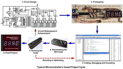
Typical Microcontroller’s based project cycle is shown on the above picture, we will use this simple cycle for practicing our Microchip PIC assembly language skill through various experiments. Ok now let’s take a look at the circuit design for this tutorial:

The Microchip PIC 12F683 has 6 general purpose I/O; GP0 to GP5, the above circuit is suitable for learning such as simple digital I/O up to the advanced topics such as using the PIC 12F683 ADC and PWM peripherals.
The Shopping Bag
For this tutorial you will need this following hardware and software:
1. Microchip PIC 12F683 PDIP microcontroller with the datasheet downloaded from Microchip site (www.microchip.com)
2. One breadboard or prototype board with an adequate amount of jumper
3. ¼ Watt resistor: 1K (2), 10K (1), 330 (1), 10K Trimport (1)
4. Capacitor: 100nF (1), 10nF (1)
5. One 3mm LED (Light Emitting Diode)
6. One 5 Volt regulated power supply or you could use 3 AA/AAA size alkaline battery for the project power source
7. Microchip PICKit2 programmer for downloading the HEX code
8. Microchip MPLAB IDE for coding, debugging and compiling the code; downloaded from Microchip site.
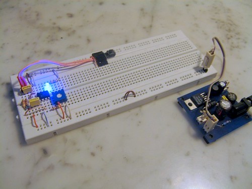
Bellow is the prototype of the Microchip PIC12F683 microcontroller circuit used in this tutorial.
My first Assembly Program
“Hello World” one of the famous phrase introduced by Brian W. Kernighan and Dennis M. Ritchie on their famous book “The C Programming Language” when they first introduced this new programming language many years ago. As they said “the only way to learn a new programming language is by writing programs in it“. This is true, first time you don’t have to understand the code at all, but by writing the code by your self (I mean laterally not just cut and paste the code), compiling/simulating the code, downloading the code to the microcontroller and running the code you will get the excitement to learn further for having good understanding of the code you just wrote. Ok let’s write your first Hello World program, first open your Microchip MPLAB IDE application, from Project menu choose Project Wizard, after welcome screen you will get the device selection screen, choose the PIC12F683:

Next is the language Toolsuite selection screen, select the Microchip MPASM Toolsuite:

The next step brings you to the new project file creation screen; enter the full path of your project name:

The next step just press next to continue (currently you don’t have any existing file to add) to the summary screen, after examining the summary information you could continue by pressing the finish button. Activate the Project and Output View from View menu; from File create New file and save it as HelloWorld.asm in your project directory.

Next on the project windows; right click on the Source Files folder and add files “HelloWorld.asm” to the project; now you could start typing your first Microchip PIC assemblerlanguage program as follow:
;******************************************************************************
;  File Name    : HelloWorld.asm
;  Version      : 1.0
;  Description  : Hello World Program
;  Author       : RWB
;  Target       : Microchip PIC 12F683 Microcontroller
;  Compiler     : Microchip Assembler (MPASM)
;  IDE          : Microchip MPLAB IDE v8.00
;  Programmer   : PICKit2
;  Last Updated : 18 March 2009
; *******************************************************************
#include <p12F683.inc>
     __config (_INTRC_OSC_NOCLKOUT & _WDT_OFF & _PWRTE_OFF & _MCLRE_OFF & _CP_OFF & _IESO_OFF & _FCMEN_OFF)
     cblock 0x20
Delay1                    ; Define two 8-bit variables for the
Delay2                    ; delay loop: Delay1 and Delay2
     endc

     org 0                ; Start at flash address 0
Start:
     bsf    STATUS,RP0    ; Select Registers at Bank 1
     movlw  0x70
     movwf  OSCCON        ; Set the internal clock speed to 8 Mhz
     clrf   TRISIO        ; Set all General Purpose I/O to output
     clrf   ANSEL         ; Make all ports as digital I/O
     bcf    STATUS,RP0    ; Back to Registers at Bank 0

MainLoop:
     bsf    GPIO,2        ; Set GP2 Output To High
     call   Delay         ; Call Delay Subroutine
     bcf    GPIO,2        ; Clear GP2 Output To Low
     call   Delay         ; Call Delay Subroutine
     nop                  ; No Operation
     goto   MainLoop      ; Goto MainLoop
Delay:
     movlw  0xFF
     movwf  Delay2
DelayLoop1:
     movlw  0xFF
     movwf  Delay1
DelayLoop2:
     decfsz Delay1,f      ; Decrease Delay1, If zero skip the next instruction
     goto   DelayLoop2    ; Not zero goto DelayLoop2
     decfsz Delay2,f      ; Decrease Delay2, If zero skip the next instruction
     goto   DelayLoop1    ; Not zero goto DelayLoop1
     return               ; Return to the Caller
     end
; EOF: HelloWorld.asm
After typing the above assembly program (remember that the __config statement is preceded by two underline character) it’s time to compile and simulating the code using Microchip MPLAB IDE, but before we do that; first we will activate the Watch and Special Function Registers windows by selecting them from the View menu; now add these following SFR (special function registers) on the Watch window by selecting it from the combo list and press the Add SFR button: STATUS, WREG, OSCCON, TRISIO, ANSEL and GPIO; Next we will add the two variables (Delay1 and Delay2) used in Delay subroutine start from address 0x20 to 0x21 by right clicking on the Watch window then click the Add… menu, the Add Watch window will appear as follow:

Change the Start Address to 0x20 and the End Address to 0x21, after clicking the Add Address you could organize these two new windows like this following picture:

Secondly we will choose the MPLAB simulator program, from the Debugger menu -> Select Tools -> MPLAB SIM. Finally we will set the MPLAB simulator frequency to 8 Mhz as we use in the real PIC12F683 microncotroller; from the Debugger menu -> Setting…:

Change the Processor Frequency to 8 Mhz and leave the other setting to their default value. Now you are ready to compile and simulating your code.
Compiling and Simulating the Code
I always mention through the entire introduction tutorials both AVR and PIC microcontroller that simulating or debugging the code is one of the essential steps that should be taken before downloading the HEX file to the microcontroller even for the experience embedded system designer; they should go through this step. Ok let’s compile the code first by selecting Project menu and click Build All or you could use the Ctrl+F10 short key. If there are no typo errors than you will have clean output result as this following screen:

Now you are ready to run your code on the Microchip MPLAB IDE Simulation; from the Debugger menu click the Step Into or you could use the F7 short key; this will bring you to the first PIC microcontroller assembly command: bsf STATUS, RP0 as shown on this following picture:

You could reset the simulation anytime by pressing the F6 short key (Processor Reset command) and start all over again. Each time you press the F7 key (Step Into) you could always view the registers value on the Watch window. When it point to the call Delay statement, because this subroutine will take a long time to be executed by the Step Into command, alternatively you could use the Step Over command (F8) to go through (pass) this subroutine; you could change the 0xFF value with 0x02 value if you still want to Step Into this subroutine for getting better understanding of how the subroutine program work.
Delay:
     movlw  0x02
     movwf  Delay2
DelayLoop1:
     movlw  0x02
     movwf  Delay1
DelayLoop2:
     decfsz Delay1,f      ; Decrease Delay1, If zero skip the next instruction
     goto   DelayLoop2    ; Not zero goto DelayLoop2
     decfsz Delay2,f      ; Decrease Delay2, If zero skip the next instruction
     goto   DelayLoop1    ; Not zero goto DelayLoop1
     return               ; Return to the Caller
Remember to restore back the original value (0xFF) before you downloading the final HEX code; otherwise the delay will be too short to be noticed by our eyes.
Downloading the HEX Code
After compiling and simulating your code it’s time to download the code using the Microchip PICKit2 programmer, connect the PICKit2 ICSP (Microchip In Circuit Serial Programming) port to your PIC12F683 microcontroller pins then from the Programmer menu Select Programmer -> PicKit2; You will get this following result on the output windows of the Microchip MPLAB IDE:

Now you are ready to download the HEX code by selecting the Program from the Programmer menu:


Now you could enjoy you hard work by watching your first Microchip PIC12F683 microcontroller “Hello World” Assembly Programming:
The Final Thought
You should practicing all the steps mentioned on this tutorial, this will give you the feel of building/prototyping the basic of Microchip PIC12F683 microcontroller project, Coding, Compiling, Simulating and finally downloading the HEX code. I hope this will give you enough fuel to gain more understanding to the code you just wrote on my second part of this tutorial.
Bookmarks and Share


Related Posts
8 Responses to “Introduction to Microchip PIC Assembler Language – Part 1”
Comment by rwb.
INP ENB stands for “Input Enable” (enable the switch input) while LED ENB stands for “LED Enable” (enable the LED output). On breadboard you simply replace both of these pin jumpers with cable.
The thick line is called the bus line, it is a simplified replacement for drawing many lines in the electronics circuit schematic, therefore it could be drawn in 3 different places to enhance clearness.
Comment by No1Daemon.
Thanks. I see it now. A few more questions. What type of capacitors are they? They are not polarised by looking at the symbol.
Also, my breadboard only has one power rail on each side so I have put ground on the switch side and +5V on the opposite side. I assume from your second photo which shows the pic programmer in it you have power coming from your power supply with +5v and ground on one side and just ground on the other, is that correct?
It is rather difficult even with your photos to translate from the circuit to a breadboard because this is still a little new to me but I will get there.
Comment by rwb.
Yes, you are right! You could freely place your components on breadboard as long as all connected as shown on the electronic schematic above. The capacitor I used is a non-polar MKM (Metalized Capacitor with Mixed dielectric) type capacitor.
Comment by cutthemusic.
Why did u choose that type of capacitors? Could you substitute another kind?
Comment by rwb.
Yes, you could use any non-polar capacitor type for this circuit. The MKM capacitor type is best used in hi-fi electronic circuit and it’s more expensive compared to the ceramic type. It’s happened when I build this circuit my ceramic capacitor stock is run out, therefore I just used any capacitors that available on that time.
Comment by cutthemusic.
I finally got the parts I needed for this exercise. I got the project working but the pot and switch don’t seem to do anything. When I apply power to the circuit the led flashes on and off. What is supposed to happen when I close the switch or turn the pot????
Comment by rwb.
For the first lesson the switch and potentiometer won’t do anything. To complete the lesson continue to read the “Introduction to Microchip PIC Assembler Language – Part 2” and “Building your own Simple Laser Projector using the Microchip PIC12F683 Microcontroller” articles.

Comment by No1Daemon.
Hi. I am using your post to teach myself the begginings of microchip programming using the pickit2 and this same pic, the pic12f683. Can you explain the meaning of inp ERB and led enb please?
I am learning and am trying to convert the circuit diagram to a breadboard and cannot work out what ERB is.
Also, how come the pic is drawn in the circuit in 3 different places?
Thanks
Sorry for the noob questions, we all have to start somewhere!