Blog Entry
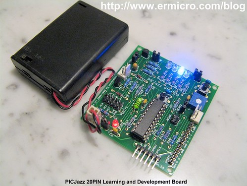
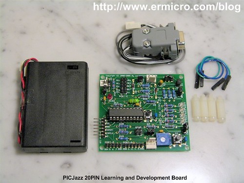
PICJazz 20PIN Learning and Development Board
November 12, 2008 by admin, under Development Board News.
The PICJazz 20PIN board from ermicro is designed to be used both as the Microchip PIC microcontroller learning and development board. The PICJazz 20PIN board is stand alone microcontroller module equipped with the latest 8-bit class Microchip midrange and high performance such as PIC16F690 or PIC18F14K50 microcontroller that could be used for wide range of applications including embedded controller, remote data logger, robotics and much more.
The PICJazz 20PIN board features:
- High performance nanoWatt technology Microchip PIC16F690 microcontroller with 4K word Self-Programmable Flash, 256 bytes EEPROM and 256 bytes Internal SRAM. Peripherals include: one 8 bit and one 16 Bit Timers/Counter, four PWM channels, 12 channels 10 bit ADC, USART, Master/Slave SPI and I2C
- Could be used with other 8,14 and 20 Pin 8-bit Microchip PIC microcontroller families such as PIC12F683, PIC16F684, PIC16F677, PIC18F14K22 and PIC18F14K50 (USB)
- Designed to be used as the PICAXE microcontroller development platform such as PICAXE 8M, 14M, 20M and 20×2 families
- Four 3mm blue LED attached to the PORTC
- Reset Button
- One configurable port digital user switch
- One configurable port user trimmer potentiometer (trimport) for analog input
- High speed instruction throughput using internal 8 MHz (PIC16F690) and 16MHz (PIC18F14K50) oscillator
- RS232 Level converter for communicating with other equipment such as PC
- Separate RS232 port to download the program using PICAXE Programming Editor from Education Revolution Ltd
- Fully supported by Microchip MPLAB IDE v8.x, Microchip C18, HI-TECH C PRO PIC10/12/16 MCU Families and HI-TECH PIC18 compiler
- Standard Microchip ICSP Port to re-programmed the PICJazz 20PIN board using Microchip PICkit2 programmer
- Example project using PICJazz 20PIN board could be found on http://www.ermicro.com/blog
- The PICJazz 20PIN board demo program source code is include in the CDROM; this program demonstrate the capability of the PICJazz 20PIN board such as accessing the RS232 port, using the user switch, using the user analog input (trimport) and running the four 3mm blue LED.

Running the PICJazz 20PIN demonstration program
The PICJazz 20PIN Board comes preprogrammed with a demonstration program (PICJazz16F690Demo.c). To use this program, connect the PICJazz 20PIN to the battery power that comes with the board. The demo program will display the chasing light on the four blue LED (mode 0). Rotate the user trimport, labeled VR, and the chasing LED speed will change in different rate. Press the user switch, labeled S2, and now the board will blink all the LED (mode 1). Press this user switch once again will bring you to the number guessing game through the RS232 port (mode 2).

The number guessing game could be monitored or played using windows Hyperterminal or puTTY program on your computer. Connect the RS232 cable which come with the board directly to your computer COM or through USB to RS232 converter and start the Hyperterminal or puTTY program using this following setting: 9600 baud rate, 8 bit Data, Parity: None and 1 Stop Bit.

Start the HyperTerminal program (Windows XP) by selecting start -> All Programs -> Accessories -> Communications -> HyperTerminal as follow:

Name the connection as piccom or whatever you like to call it; than click the Ok button, chose the communication port as follow:

Click the Ok button and set the communication data frame as follow:

Click the Ok button and it will bring you to the terminal emulation screen; then set the properties of the terminal from menu File -> Properties and choose the Setting tab; select ANSI for the terminal emulation:

Now press the Ok button and it will bring you back to the windows HyperTerminal’s screen as follow:

After pressing the user switch (S2) twice, the demo program shows the PICJazz 20PIN board number guessing game (mode 3) as follow:

You could enter “x” character at any time to bring the program back to the PICJazz 20PIN chasing LED demo program (mode 0).
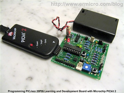
Programming PICJazz 20PIN Using the Microchip PICKit2 or PICKit3
We recommend using the Microchip PICkit2 or PICKit3 to program the PICJazz 20PIN board, the board comes with the standard Microchip ICSP (In Circuit System Programming) pins which could be connected directly to the Microchip PICkit2.
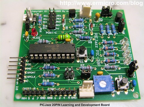
PICJazz 20PIN Board Ports
The PICJazz 20PIN board has three general purposes I/O PORT: PORT-A (5 I/O), PORT-B (4 I/O) and PORTC (8 I/O) and one Microchip standard 6 pins ICSP (In Circuit System Programming) PORT as shown on this following picture:

PICJazz 20PIN Board Jumpers Function
There are four jumpers on the PICJazz 20PIN Board named: J1, J2, J3, J4, J5 and J6; the following table shows the function of these jumpers:


Down loading PICJazz 20PIN board Sample Program
Run the MPLAB v8.x (assuming the HI-TECH C PRO V9.60 program is already installed on your computer) and load the following sample C program (myfirstc.c) on the project or you could use your own program:
/* ***************************************************************************
**  File Name    : myfirstc.c
**  Version      : 1.0
**  Description  : My First PIC C Programming
**  Author       : RWB
**  Target       : PICJazz 20PIN Board: PIC16F690
**  Compiler     : HI-TECH C PRO PIC10/12/16 MCU Family(Lite) Version 9.60PL1
**  IDE          : Microchip MPLAB IDE v8.30
**  Programmer   : PICKit2
**  Last Updated : 08 Dec 2008
** ***************************************************************************/
#include <pic.h>
/*   PIC Configuration Bit:
**   INTIO     - Using Internal RC No Clock
**   WDTDIS    - Wacthdog Timer Disable
**   PWRTEN    - Power Up Timer Enable
**   MCLREN    - Master Clear Enable
**   UNPROTECT - Code Un-Protect
**   UNPROTECT - Data EEPROM Read Un-Protect
**   BORDIS    - Borwn Out Detect Disable
**   IESODIS   - Internal External Switch over Mode Disable
**   FCMDIS    - Monitor Clock Fail Safe Disable
*/
__CONFIG(INTIO & WDTDIS & PWRTEN & MCLREN & UNPROTECT \
  & UNPROTECT & BORDIS & IESODIS & FCMDIS);
/* Using Internal Clock of 8 Mhz */
#define FOSC 8000000L
/* Delay Function */
#define	delay_us(x) { unsigned char _dcnt; \
			         _dcnt = (x)/(12000000/FOSC)|1; \
			         while(--_dcnt != 0) continue; }
void delay_ms(unsigned int cnt)
{
  unsigned char i;
  do {
    i = 4;
    do {
      delay_us(164);
    } while(--i);
  } while(--cnt);
}
void main(void)
{
  OSCCON=0x70;         /* Select 8 Mhz internal clock */
  TRISB = 0x00;	   /* Set All on PORTB as Output */
  ANSEL = 0;           /* Set PORT ANS0 to ANS7 as Digital I/O */
  ANSELH = 0;          /* Set PORT ANS8 to ANS11 as Digital I/O */
  PORTB=0x00;
  for(;;) {
    PORTB = 0xFF;       /* Turn On Port RB0  */
    NOP();
    delay_ms(200);
    PORTB = 0x00;       /* Turn Off Port RB0 */
    NOP();
    delay_ms(200);
  }
}
/* EOF: myfirst.c */
Connect the PICkit2 programmer to the USB port and the programmer ICSP port to the PICJazz 20PIN board ICSP port; turn the PICJazz 20PIN power. From the MPLAB IDE menu select Programmer -> Select Programmer -> Pickit2 it will automatically configure the connection and display it on the PICkit2 tab Output windows:

Compile your project code, from menu select Project -> Build or press F10:

Now you are ready to down load the code from MPLAB IDE menu select Programmer -> Program; this will down load the HEX code into the PICJazz 20PIN board:

Disconnect the ICSP port from the PICJazz 20PIN board and press the reset switch (S1); you will see the blinked LED.
Working with the PICAXE Microcontroller
The PICAXE microcontroller actually is an ordinary Microchip PIC microcontroller that has been specially programmed with BASIC language interpreter on its memory (flash or EEPROM). With the PICAXE Programming Editor from Education Revolution Ltd in UK, the PICAXE microcontroller becomes one of the best embedded system platforms for the newcomer.

The PICJazz 20PIN development and learning board is designed to support the PICAXE; to use the PICAXE microcontroller we have to remove pin jumpers J4 and J5; then put it on pin jumper J6 to activate the PICAXE serial down loader RS232 port. For this tutorial purpose you reconfigure the user switch and analog input port using the female to female connector which comes with the PICJazz 20PIN board as shown on this following picture:
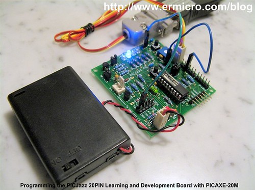
After replace the PICJazz 20PIN board microcontroller with the PICAXE-20M, connect the user switch to RC3 port and analog trimport to RA4 port. Use the PICJazz 20PIN board PICAXE serial downloader to download this code from the PICAXE Programming Editor.
'***************************************************************************
'  File Name    : blinkled.bas
'  Version      : 1.0
'  Description  : PICAXE Blinking LED
'  Author       : RWB
'  Target       : PICJazz 20PIN Learning Board
'  Intepreter   : PICAXE Firmware version 3.B
'  IDE          : PICAXE Programming Editor Version 5.2.6
'  Programmer   : PICAXE Programming Editor Version 5.2.6
'  Last Updated : 22 September 2009
'***************************************************************************
' Use PICAXE 20M
#picaxe 20M
' Assigned Variable
symbol adc_val = b0
symbol high_val = b1
symbol low_val = b2
symbol sign = b3
let pins = %00000000 ' Reset all Output Pins
sign = 0             ' Default Running LED
main:
  ' Read User Switch on Input IN3
  if pin3 = 0 then
    sign=sign XOR 1
  endif

  ' Read Trimport ADC Value on Input IN7
  readadc 7,adc_val

  if sign = 0 then
    for high_val = 2 to 4
      low_val=high_val - 1
      low low_val
      high high_val

      pause adc_val
    next high_val

    for high_val = 3 to 2 step -1
      low_val=high_val + 1
      low low_val
      high high_val

      pause adc_val
    next high_val
  else
    let pins = %00000000
    pause adc_val
    let pins = %00011100
    pause adc_val
  endif

  goto main      ' Back to main loop
  end
' EOF: blinkled.bas

You could use the Option button to configure the development environment (e.g. PICAXE type, internal oscillator clock, etc) and do the syntax check with the Syntax button to check your syntax as well as the program size.

Pressing the Program button will down load your BASIC program token to the PICAXE microcontroller and then the PICAXE BASIC interpreter automatically will execute the code.
PICJazz 20PIN Board Specification:
1. Microchip® PIC16F690 Microcontroller running on maximum 8 MHz internal clock
2. Four 3mm blue LEDs output
3. RS232 Level Shifter
4. PICAXE Programming Editor RS232 serial down loader Port
5. One User Switch
6. One User Analog Input (Trimport)
7. Reset Button
8. Board size 68 x 64 mm
PICJazz 20PIN Board Power Requirement:
Well regulated power supply: 3 Volt – 5 Volt
Accessories include with the PICJazz 20PIN Board:
1. One PICJazz 20PIN RS232/PICAXE downloader Cable
2. One 3xAA 1.5 Volt Battery Holder (battery not include)
3. 4 x Metal PCB Standoff
4. 2 x female to female Conector Cable
5. 1 CD User Guide and Sample Program
Get the PICJazz 20PIN Model 1 (PIC16F690) Now !
Bookmarks and Share


Related Posts
6 Responses to “PICJazz 20PIN Learning and Development Board”
Comment by rwb.
The easy one is to use the Microsoft Visual Basic Express 2005/2008/2010 Edition and use the Serial Port object (IO.Ports.SerialPort) for reading the RS232 COM port data, save it to the text file using the File object (System.IO.File), and StreamWriter object (System.IO.StreamWriter). You could get a lot of example on this topic on the net.
Comment by shadrack.
thanks for all ua comments am sorted out in nistances where i was stuck
Comment by edbart.
Hi!
really a great tutorial, especially on the link below all the programs were super commented, drafts, schemes … simply wow.
The only problem is that it is not possible to log in and to send a commentary.
Comment by rwb.
Thank you, its because the project article has reached its maximum comments
Comment by klyx.
Hello, i know this is old post but i planned to create my own dev-board based on PICjazz and wanna ask some question:
1. Would you mind if someone (eg: me) replicate and/or modify your PICjazz (or any board on this blog) schematic for commercial purpose ?
2. Where you got your picaxe chips ? direct form rev-ed or somewhere else ? i got my 20X2 from rev-ed but it will nice to know the alternative
best regards,
mike

Comment by p4n4k4ts.
Hi! The PICJazz is a perfect tool! Great for either simple or more advanced projects!
I would like to ask if we could somehow create a file to save the results to our PC?
For example how could we save the numbers we choose during the guessing game or even the different values of the trimport?
Thank for your time and your valuable help