Blog Entry
Build Your Own Transistor Based Mobile Line Follower Robot (LFR) – First Part
July 11, 2009 by rwb, under Robotics.
The mobile line follower robot is a type of mobile robot with only has one specific task which is to follow the line made with black tape over the white background or vise verse. The LFR perhaps is one of the most popular robot build by the roboticists. What makes this LFR is so popular, I think because of its simplicity and yet it could be used as the teaching tools of how we could implement the industrial standard control system such as the PID (Proportional Integral Deferential) control system on this robot. Another factor probably is the increase of the LFR annual tournament conducted in many countries.
The basic principal of the line follower robot actually almost the same as the light follower robot, but instead of tracking the light the LFR sensor is used to track the line, therefore by differentiating the line color and it’s surrounding (black over white or vise verse) any light sensitive sensor could be used to navigate the mobile robot to follow this track.

Base on the above fact, I designed the simplest possible electronics circuit that use the navigation principal shown above to track the black tape line.
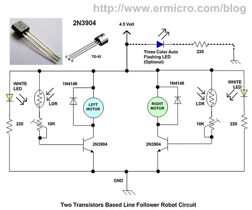
The 2N3904 NPN Bipolar Junction Transistor (BJT) is designed to operate as the current gainer amplifier; this means we operate the 2N3904 transistor in its linear region. The advantages of using the transistor in its linear region is; the transistor collector current passed through the DC motor will varying according to the base current which controlled by the LDR (Light Dependent Transistor) and 10 K trimmer potentiometer (trimpot). Therefore the current through the DC motor will vary according to the light intensity received by the LDR.
Using this simple principal we could easily used this circuit to track the black tape by locating the LDR and the white LED in such a way that the LDR will receive less light from the white LED when the LDR position right on top of the black tape and this will make the DC motor to turn slowly (less collector current). When the LDR position outside the black tape (on the top of the white background) the LDR will receive more light from the white LED; this will make the motor to turn faster (more collector current).

The trimpot is use to adjust the DC motor speed, while the 1N4148 diode is use to protect the transistor again the EMF (Electromotive Force) generated by the DC motor inductor when its switch off. The key of successfully building this circuit is heavily depend on the geared DC motor we choosed.
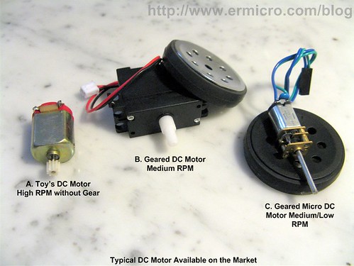
You have to choose the geared DC motors which rated 5 volt that have low power consumption (small current) as the 2N3094 transistor only allowed max 100 mA current on its collector (you could replace it with 2N2222A transistor, max 800mA) and try to use a low RPM (rotation per minute) geared DC motor (remember must be the geared DC motor). The lower RPM is required here because the LDR has a slow response comparing to other light sensitive component (e.g. photo transistor), so the Line Follower Robot could keep follow the black track line. You could always experiment with your own geared DC motor speed on different track’s route by adjusting the 10 K Ohm trimport.
One of disadvantage using the transistor on its linear region to control the DC motor’s speed is the power dissipation (power loss as heat) on the transistor especially if we use large power DC motor, the common and efficient method to control the motor’s speed is to use the PWM (pulse width modulation) which make the transistor on and off rapidly; but for the geared DC motor used in this Line Follower Robot project we simply take advantage of the transistor in its linear region to change its speed (i.e. by changing the transistor collector current). You could read more information about building the PWM based Line Follower Robot on “The LM324 Quad Op-Amp Line Follower Robot with Pulse Width Modulation” project on this blog
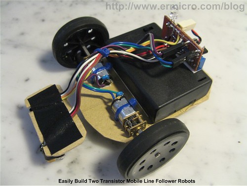
This line follower robot use what is called the “differential drive” steering method, which use two independent motor mounted in fixed positions on the left and right side of robot’s chassis. This mean by slowing the rotation speed of the left DC motor will make the robot to arc to the left and slowing the rotation speed of the right DC motor will make the robot to arc to the right. If both motor rotate at the same speed than the robot will simply go straight as shown on this following picture.

Therefore by arching to the left and to the right or go straight the robot could easily follow the black line track. As you know how this two transistors line follower robot circuit works, now its time to build the robot chassis.
The LFR Chassis Construction
The LFR construction in this tutorial is very simple as I just use a 1 mm cardboard for the main body construction and use caster (the third wheel) made from bead and paperclip as shown on my previous posted blog Building BRAM your first Autonomous Mobile Robot using Microchip PIC Microcontroller.

By using this easy to handle construction material hoping you could easily build this Line Follower Robot, these following pictures show how to assembly all these parts together.
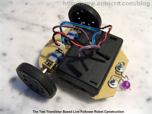
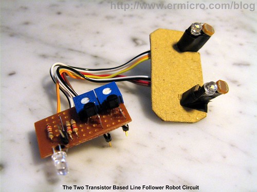
I use double tape to hold the 3 x AA (4.5 volt) battery holder and the micro geared DC motor (now you understand how important this double tape to the robot’s builder); the DC motor also is reinforced with the plastic cable’s ties. The electronics component is soldered on the 18 x 38 mm prototype PCB and I just use the duct tape to hold the LDR and LED together as shown on the above circuit. To make it more interesting I put one three colors auto flashing LED for the indicator.

Bellow is the complete list of material and electronics component used to build this line follower robot:
1. Thick paper (1 mm), double tape, duct tape, plastic cable’s ties
2. One paper clip and bead for the caster (the third wheel)
3. Adequate Bolts and Nuts
4. One 3 x AA Battery holder and 3 x AA (1.5 Volt Alkaline) Battery
5. Two micro geared DC motor rated 5 volt, unloaded RPM < 50, unloaded current: < 50mA
6. 18 x 38 mm prototype PCB
7. Two 220 Ohm 0.25 watt resistor
8. Two LDR (about 2 ~ 5K Ohm in the bright light and 100K Ohm in the dark).
9. Two 3mm white LED
10. One auto flashing RGB LED with one 220 ohm resistor 0.25 watt (optional)
11. Two 10 K Ohm Trimmer Potentiometer
12. Two 1N4148 Diodes
13. Two 2N3904 or 2N2222A Transistors.

Now it’s time to show the capabilities of this simple and easy to build line follower robot.
The Final Thought
As you’ve seen from the demo video above this two transistors Line Follower Robot sometimes out perform many of the microcontroller based line follower robot designed and for sure using more complex circuit (e.g. the 8-bits microcontroller and the motor controller) and not to mention the microcontroller’s programming; which eventually do the same job as demonstrated by this simple two transistors based line follower robot.
For higher speed line follower robot with more complex track, we need to use the microcontroller, although it’s possible to use just a discrete electronics components but its required more complex circuit which than the microcontroller based solution become more simple and cheap to be used. On my second part of the line follower robot (LFR), we will build the microcontroller’s based LFR which using more advance sensors to track the line compared to this one.
Bookmarks and Share


Related Posts
104 Responses to “Build Your Own Transistor Based Mobile Line Follower Robot (LFR) – First Part”
Comment by rwb.
Try to use a geared DC motor with small current e.g. less then 60 mA when operate normally (no load) and use the 2N2222A transistor instead of the BC639 transistor.
Comment by polaris589.
we are now made this project but the problem is that we should applied logic gates.. is it possible to used ic in this circuit? how is that possible? thanks
Comment by rwb.
Yes its possible but that will change the entire electronic circuit schematic and its beyond the purpose of this project. You could read more about the Line follower Robot on “Build Your Own Microcontroller Based PID Control Line Follower Robot (LFR) (Second Part)” and “The LM324 Quad Op-Amp Line Follower Robot with Pulse Width Modulation” articles.

Comment by aravind9948.
hi rwb
Thanks for the last comment rwb,LDRS are working properly.when i am using toy dc motors there is know rotation of motors,if i am removing motors and keeping the leds there is a response from the leds what is the problem i think there is low power from collecter so can i replace the transistor with “BC 639” if it work properly