Blog Entry
How to use I2C-bus on the Atmel AVR Microcontroller
February 4, 2009 by rwb, under Microcontroller.
I2C (read as I Squared C) bus first introduced by Philips in 1980, because of its simplicity and flexibility the I2C bus has become one of the most important microcontroller bus system used for interfacing various IC-devices with the microcontroller. The I2C bus use only 2 bidirectional data lines for communicating with the microcontroller and the I2C protocol specification can support up to 128 devices attached to the same bus. Today many I2C IC-devices available on the market such as Serial EEPROM, I/O Expander, Real-Time Clock, Digital to Analog Converter, Analog to Digital Converter, Temperature Sensor and many more.
The I2C protocol use master and slave method, the master which is usually the microcontroller while the slave can be any I2C devices such as Serial EEPROM, I/O Expander or even another microcontroller. All of these devices connected to the I2C bus; one for the serial data called SDA (serial data) and the other for synchronize clock called SCL (serial clock); each of these slave devices has their own individual 7 bits of the address length.

The 7 bits address consists of 4 bits device identification and 3 bits device physical address. For example if we want to use the Microchip 24AA128 I2C CMOS serial EEPROM, the first 4 bits for this device identification is “1010” and the last 3 bits could be selected by setting the appropriate address at pins A0, A1 and A2 on the serial EEPROM. Therefore by using these 3 bits we could attach up to 8 Microchip 24AA128 serial EEPROM on the same I2C bus; which give you total of 8 x 16 Kbytes of memory.

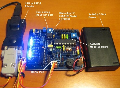
The same principal also applies to the other I2C-bus devices such as the Microchip MCP23008 8-bit I/O Expander and Dalas DS1307 Real Time Clock (see the example picture). By selecting the appropriate device address, the master can easily communicate with the entire slave devices connected to the I2C bus; the I2C bus protocol only allowed one connection to be established between master and slave at a time. With this powerful and yet simple concept you could see the enormous possibility of using these I2C bus devices for the embedded application.
In this tutorial we will use the AVRJazz Mega168 board from ermicro that has build in Microchip 24AA128 I2C serial EEPROM on the board; we will use this EEPROM for storing the LEDs data pattern and later on we will read the data and display it to the LEDs attached to the AVR ATMega168 microcontroller on the PORT D.
The principal we learn on this I2C serial EEPROM device can be applied to other I2C devices as well, the differences is only on the terms used; on the serial EEPROM we use memory address for storing and retrieving the data, while on the other I2C devices such as Microchip MCP23008 8-bit I/O expander or Dalas DS1307 Real Time Clock we use register address for writing and reading the data.
The following is the list of hardware and software used in this tutorial:
- AVRJazz Mega168 board from ermicro which base on the AVR ATmega168 microcontroller (board schema).
- WinAVR for the GNU’s C compiler
- Atmel AVR Studio 4 for the coding and debugging environment.
- STK500 programmer from AVR Studio 4, using the AVRJazz Mega168 board STK500 v2.0 bootloader facility.
- Atmel AVR ATMega48/88/168/328 Datasheet

Now let’s jump to the C code that make this happen.
//***************************************************************************
//  File Name    : i2cbus.c
//  Version      : 1.0
//  Description  : I2Cbus EEPROM AVR Microcontroller Interface
//  Author(s)    : RWB
//  Target(s)    : AVRJazz Mega168 Learning Board
//  Compiler     : AVR-GCC 4.3.0; avr-libc 1.6.2 (WinAVR 20080610)
//  IDE          : Atmel AVR Studio 4.14
//  Programmer   : AVRJazz Mega168 STK500 v2.0 Bootloader
//               : AVR Visual Studio 4.14, STK500 programmer
//  Last Updated : 28 Dec 2008
//***************************************************************************
#include <avr/io.h>
#include <util/delay.h>
#include <compat/twi.h>
#define MAX_TRIES 50
#define EEPROM_ID    0xA0        // I2C 24AA128 EEPROM Device Identifier
#define EEPROM_ADDR  0x00        // I2C 24AA128 EEPROM Device Address
#define I2C_START 0
#define I2C_DATA  1
#define I2C_STOP  2
unsigned char i2c_transmit(unsigned char type) {
  switch(type) {
     case I2C_START:    // Send Start Condition
       TWCR = (1 << TWINT) | (1 << TWSTA) | (1 << TWEN);
       break;
     case I2C_DATA:     // Send Data
       TWCR = (1 << TWINT) | (1 << TWEN);
       break;
     case I2C_STOP:     // Send Stop Condition
       TWCR = (1 << TWINT) | (1 << TWEN) | (1 << TWSTO);
       return 0;
  }
  // Wait for TWINT flag set in TWCR Register
  while (!(TWCR & (1 << TWINT)));
  // Return TWI Status Register, mask the prescaler bits (TWPS1,TWPS0)
  return (TWSR & 0xF8);
}
int i2c_writebyte(unsigned int i2c_address, unsigned int dev_id,
                  unsigned int dev_addr,char data) {
  unsigned char n = 0;
  unsigned char twi_status;
  char r_val = -1;
i2c_retry:
  if (n++ >= MAX_TRIES) return r_val;
  // Transmit Start Condition
  twi_status=i2c_transmit(I2C_START);

  // Check the TWI Status
  if (twi_status == TW_MT_ARB_LOST) goto i2c_retry;
  if ((twi_status != TW_START) && (twi_status != TW_REP_START)) goto i2c_quit;
  // Send slave address (SLA_W)
  TWDR = (dev_id & 0xF0) | ((dev_addr & 0x07) << 1) | TW_WRITE;
  // Transmit I2C Data
  twi_status=i2c_transmit(I2C_DATA);
  // Check the TWSR status
  if ((twi_status == TW_MT_SLA_NACK) || (twi_status == TW_MT_ARB_LOST)) goto i2c_retry;
  if (twi_status != TW_MT_SLA_ACK) goto i2c_quit;
  // Send the High 8-bit of I2C Address
  TWDR = i2c_address >> 8;
  // Transmit I2C Data
  twi_status=i2c_transmit(I2C_DATA);
  // Check the TWSR status
  if (twi_status != TW_MT_DATA_ACK) goto i2c_quit;
  // Send the Low 8-bit of I2C Address
  TWDR = i2c_address;
  // Transmit I2C Data
  twi_status=i2c_transmit(I2C_DATA);
  // Check the TWSR status
  if (twi_status != TW_MT_DATA_ACK) goto i2c_quit;
  // Put data into data register and start transmission
  TWDR = data;
  // Transmit I2C Data
  twi_status=i2c_transmit(I2C_DATA);
  // Check the TWSR status
  if (twi_status != TW_MT_DATA_ACK) goto i2c_quit;
  // TWI Transmit Ok
  r_val=1;
i2c_quit:
  // Transmit I2C Data
  twi_status=i2c_transmit(I2C_STOP);
  return r_val;
}
int i2c_readbyte(unsigned int i2c_address, unsigned int dev_id,
                 unsigned int dev_addr, char *data)
{
  unsigned char n = 0;
  unsigned char twi_status;
  char r_val = -1;
i2c_retry:
  if (n++ >= MAX_TRIES) return r_val;
  // Transmit Start Condition
  twi_status=i2c_transmit(I2C_START);

  // Check the TWSR status
  if (twi_status == TW_MT_ARB_LOST) goto i2c_retry;
  if ((twi_status != TW_START) && (twi_status != TW_REP_START)) goto i2c_quit;
  // Send slave address (SLA_W) 0xa0
  TWDR = (dev_id & 0xF0) | ((dev_addr << 1) & 0x0E) | TW_WRITE;
  // Transmit I2C Data
  twi_status=i2c_transmit(I2C_DATA);
  // Check the TWSR status
  if ((twi_status == TW_MT_SLA_NACK) || (twi_status == TW_MT_ARB_LOST)) goto i2c_retry;
  if (twi_status != TW_MT_SLA_ACK) goto i2c_quit;
  // Send the High 8-bit of I2C Address
  TWDR = i2c_address >> 8;
  // Transmit I2C Data
  twi_status=i2c_transmit(I2C_DATA);
  // Check the TWSR status
  if (twi_status != TW_MT_DATA_ACK) goto i2c_quit
  // Send the Low 8-bit of I2C Address
  TWDR = i2c_address;
  // Transmit I2C Data
  twi_status=i2c_transmit(I2C_DATA);
  // Check the TWSR status
  if (twi_status != TW_MT_DATA_ACK) goto i2c_quit;

  // Send start Condition
  twi_status=i2c_transmit(I2C_START);
  // Check the TWSR status
  if (twi_status == TW_MT_ARB_LOST) goto i2c_retry;
  if ((twi_status != TW_START) && (twi_status != TW_REP_START)) goto i2c_quit;
  // Send slave address (SLA_R)
  TWDR = (dev_id & 0xF0) | ((dev_addr << 1) & 0x0E) | TW_READ;
  // Transmit I2C Data
  twi_status=i2c_transmit(I2C_DATA);

  // Check the TWSR status
  if ((twi_status == TW_MR_SLA_NACK) || (twi_status == TW_MR_ARB_LOST)) goto i2c_retry;
  if (twi_status != TW_MR_SLA_ACK) goto i2c_quit;
  // Read I2C Data
  twi_status=i2c_transmit(I2C_DATA);
  if (twi_status != TW_MR_DATA_NACK) goto i2c_quit;
  // Get the Data
  *data=TWDR;
  r_val=1;
i2c_quit:
  // Send Stop Condition
  twi_status=i2c_transmit(I2C_STOP);
  return r_val;
}
int main(void)
{
   char buffer[34]= {0b00001111,0b11110000,
                     0b00000001,
    		     0b00000011,
		     0b00000110,
	  	     0b00001100,
		     0b00011001,
		     0b00110011,
		     0b01100110,
		     0b11001100,
		     0b10011000,
		     0b00110000,
		     0b01100000,
		     0b11000000,
		     0b10000000,
		     0b00000000,
		     0b00000000,
		     0b00000000,
		     0b10000000,
		     0b11000000,
		     0b01100000,
		     0b00110000,
		     0b10011000,
		     0b11001100,
		     0b01100110,
 	             0b00110011,
		     0b00011001,
		     0b00001100,
		     0b00000110,
		     0b00000011,
		     0b00000001,
		     0b00000000,
		     0b00000000,
		     0b00000000,
		     };

  char data,id1,id2;
  unsigned int dev_address,i,idelay;

  DDRD=0xFF;                   // Set PORTD as Output
  PORTD=0x00;                  // Set All PORTD to Low
  /* Initial ADC Peripheral for User's Trimpot Input */
  ADMUX=0x00;	               // Select Channel 0 (PC0)
  // Initial the ADC Circuit
  ADCSRA = (1<<ADEN) | (1<<ADPS2) | (1<<ADPS1);
  // Free running Mode
  ADCSRB = 0x00;
  // Disable digital input on ADC0 (PC0)
  DIDR0 = 0x01;
  /* Initial TWI Peripheral */
  TWSR = 0x00;   // Select Prescaler of 1
  // SCL frequency = 11059200 / (16 + 2 * 48 * 1) = 98.743 khz
  TWBR = 0x30;   // 48 Decimal

  // Read the EEPROM ID
  dev_address=0;              // Start at Address 0
  i2c_readbyte(dev_address,EEPROM_ID,EEPROM_ADDR,&id1);
  i2c_readbyte(dev_address + 1,EEPROM_ID,EEPROM_ADDR,&id2);
  // Write to EEPROM if no ID defined
  if (id1 != buffer[0] || id2 != buffer[1]) {
    for(i=0;i < 34;i++) {
      i2c_writebyte(dev_address + i,EEPROM_ID,EEPROM_ADDR,buffer[i]);
      _delay_us(1);
    }
  }

  // Initial Delay Value
  idelay=100;

  for(;;) {
    for(i=2;i < 34;i++) {
      // Start conversion by setting ADSC on ADCSRA Register
      ADCSRA |= (1<<ADSC);
      // wait until convertion complete ADSC=0 -> Complete
      while (ADCSRA & (1<<ADSC));
      // Get the ADC Result
      idelay = ADCW;
      // Read the EEPROM
      i2c_readbyte(dev_address + i,EEPROM_ID,EEPROM_ADDR,&data);
      // Put data to the PORTD
      PORTD=data;
      _delay_ms(idelay);          // Delay
    }
  }

  return 0;
}
/* EOF: i2cbus.c */
Inside the C Code
The program starts by initializing the ATmega168 ports used and continue with the ADC and the TWI (two wire interfaces) peripherals initiation. The TWI is the Atmel implementation of I2C-bus protocol specification, I don’t know why they named it TWI instead of I2C (perhaps it has something to do with the Philips I2C trademark); Atmel said on the datasheet that the TWI protocol is fully compatible with the I2C-bus protocol; so in other word TWI is the Philips I2C-bus clone from Atmel.
This program basically work by checking the identification marks on the serial EEPROM (0b00001111 and 0b1111000), if not exist than store the LED’s output pattern to it; than inside the infinite loop we just retrieve the serial EEPROM data and put it on the AVR ATMega168 PORT-D. On this project we also use the ADC peripheral to read the user’s analog trim port to control the delay speed of the running LED’s pattern read from the serial EEPROM.
The better implementation is to have two mode of operation; the first mode is to read the LED’s pattern from the computer through the COM (RS232) port and store it to the serial EEPROM and the second mode is to read the serial EEPROM and display it. But to keep the I2C bus learning topics as simple as possible, we just use the static data array (buffer[34]) for keeping the initial LED’s pattern.
Bellow is the description of all functions used in this code:
- i2c_writebyte() function is used to write or store 8-bits data on the I2C devices on specified I2C device address or register
- i2c_readbyte() function is used to read the 8-bits data on the I2C devices on specified I2C device address or register
- i2c_transmit() function is called by the two function above to transmit the data to the I2C device.
I2C Bus Clock (SCL)
As mention before that the I2C-bus used only 2 lines for communicating among the I2C devices; because it use the serial data transfer method therefore the I2C protocol use a clock pulse (SCL) together with the data bits (SDA) for synchronization, each of these data bits is accompanied by the pulse clock on the bus.

The I2C-bus clock frequency could be selected by using the TWI status register (TWSR) and TWI Bit Rate Generator register (TWBR)


Most of I2C devices typically can operate up to maximum 100 kHz of SCL frequency, but some of the I2C devices such as Microchip 24AA128 serial EEPROM can operate up to 400 kHz. Therefore by setting the SCL frequency near 100 kHz; it should work with most of the I2C devices. The SCL clock frequency can be calculated using this following formula:

Setting the TWPS1 = 0 and TWPS0 = 0 in the TWSR register (prescaler value 1); setting the TWBR register to 48 (30 hexadecimal) and with the AVRJazz Mega168 board frequency of 11059200 Hz, we could calculate the SCL frequency as follow:
SCL Frequency = CPU Clock / ((16 + 2 (TWBR) x (Prescaler Value))
SCL Frequency = 11059200 / (16 + 2 x 48) = 98.743 kHz
The C code bellow is used to set the SCL Frequency:
/* Initial TWI Peripheral */
TWSR = 0x00;   // Select Prescaler of 1
// SCL frequency = 11059200 / (16 + 2 * 48 * 1) = 98.743 Khz
TWBR = 0x30;   // 48 Decimal
I2C Bus Data (SDA) Write Operation
Writing to the I2C devices actually is a complex task if we have to do it manually, fortunately the complexity of I2C-bus protocol has been handled by the Atmel AVR TWI peripheral, therefore the only thing we have to do is to instruct and read the status of this TWI peripheral; all of the complex arbitration or handshaking between master and slave will be done by TWI peripheral. The following is time diagram show the explanation of how we store the data to the I2C serial EEPROM:

From the time diagram above we begin the connection by sending the START condition. This START condition is automatically generated by the TWI peripheral inside the AVR microcontroller.

By setting TWINT=1 (interrupt flag bit), TWSTA=1 (start condition bit) and TWEN=1 (enable TWI bit), in the TWCR register; the TWI will send the START condition to the I2C bus when it available. Then we just wait until the TWI peripheral confirm that it has sent the START signal to the bus; this can be done by waiting for the TWINT bit in register TWCR to be set (logical “1“) by the TWI peripheral.
// Transmit Start Condition
twi_status=i2c_transmit(I2C_START);
The C code in the i2c_transmit() function with I2C_START argument:
TWCR = (1 << TWINT) | (1 << TWSTA) | (1 << TWEN);
// Wait for TWINT=1 in the TWCR Register
while (!(TWCR & (1 << TWINT)));
// Return TWI Status Register, mask the prescaler bits (TWPS1,TWPS0)
return (TWSR & 0xF8);
This TWI setting is a little bit confusing, you see; we activated the TWI peripheral by setting the TWINT=1 (logical “1“) and than we have to wait this interrupt flag to become logical “1“?; This is what actually happen, as soon as the TWI peripheral active, it will automatically reset this interrupt flag bit to logical “0” and when it’s done the TWI peripheral will set this interrupt flag to logical “1“. Therefore by using the C while statement and masking the TWINT bit in TWCR register, we could wait until the TWINT bit being set by the TWI peripheral.
The i2c_transmit() function is use to encapsulate the repetition process of SEND and WAIT, this function will return the TWSR register status with TWPS1 and TWPS0 bits being masked. The TWSR register status macro has been defined in the compat/twi.h include file, therefore using this predefine macro; we could decide whether to continue, retry the process or to quit for error (for the complete explanation of the TWI status register, please refer to the AVR ATMega168 datasheet).
// Check the TWI Status
if (twi_status == TW_MT_ARB_LOST) goto i2c_retry;
if ((twi_status != TW_START) && (twi_status != TW_REP_START)) goto i2c_quit;
The next process is to select which I2C device we want to talk to; this can be done by sending the slave address (4 bits device ID and 3 bits physical address) and the write bit (TW_WRITE = 0, defined in the compat/twi.h include file) and we wait for the slave response.
// Send slave address (SLA_W)
TWDR = (dev_id & 0xF0) | ((dev_addr & 0x07) << 1) | TW_WRITE;
// Transmit I2C Data
twi_status=i2c_transmit(I2C_DATA);
// Check the TWSR status
if ((twi_status == TW_MT_SLA_NACK) || (twi_status == TW_MT_ARB_LOST)) goto i2c_retry;
if (twi_status != TW_MT_SLA_ACK) goto i2c_quit;
We put the slave address and the write bit to the TWDR register and again using the i2c_transmit() function with I2C_DATA argument to transmit the data and wait for the status returned by this function. When the selected I2C device response with the acknowledge signal; which mean the I2C slave device acknowledge of the address we sent than we could continue to send the data; first we select the memory address and next the data we want to store in the serial EEPROM device.
After successful sending the data finally we close the master/slave connection by sending the STOP condition to the I2C-bus.
// Send Stop Condition
twi_status=i2c_transmit(I2C_STOP);
The whole I2C-bus write operation C program is implemented in the i2c_writebyte() function.
I2C Bus Data (SDA) Read Operation
The I2C read operation is consists of writing and reading to and from the I2C devices as shown on this following time diagram:

The write process is used to tell the serial EEPROM that we would retrieve the data from selected EEPROM address; this process is similar to the write operation explained above. After we tell the serial EEPROM which address we would like to read than we enter the read operation by again sending the RESTART condition (same with START condition) and assign the 7 bits of I2C slave address with the READ status bit (TW_READ = 1).
// Send slave address (SLA_R)
TWDR = (dev_id & 0xF0) | ((dev_addr << 1) & 0x0E) | TW_READ;
// Transmit I2C Data
twi_status=i2c_transmit(I2C_DATA);

// Check the TWSR status
if ((twi_status == TW_MR_SLA_NACK) || (twi_status == TW_MR_ARB_LOST)) goto i2c_retry;
if (twi_status != TW_MR_SLA_ACK) goto i2c_quit;
Notice that because the WRITE and READ operation return different status value in the TWSR register, the compat/twi.h include file use different macro name to define it (TW_MT_SLA_ACK versus TW_MR_SLA_ACK). After receiving the slave acknowledge now we are ready to read the I2C data by sending the SEND data instruction and waiting for data transfer in the TWDR register.
// Read I2C Data
twi_status=i2c_transmit(I2C_DATA);
if (twi_status != TW_MR_DATA_NACK) goto i2c_quit;
// Get the Data
*data=TWDR;
The whole I2C-bus read operation C program is implemented in the i2c_readbyte() function.
For other I2C devices such as Microchip MCP23008 8-bit I/O Expander, Dalas DS1307 Real Time Clock, etc; the C code presented here could be use as the basic program to write or read from these devices by changing the appropriate I2C device identification, physical address and device register address (memory address).
#define DEVICE_ID    0xA0        // I2C 24AA128 EEPROM Device Identifier
#define DEVICE_ADDR  0x00        // I2C 24AA128 EEPROM Device Address
#define DEVICE_REGISTER   0x00   // I2C Device Register
...
...
...
// I2C Device Write
i2c_writebyte(DEVICE_REGISTER,DEVICE_ID,DEVICE_ADDR,buffer[i]);
...
...
// I2C Device Read
i2c_readbyte(DEVICE_REGISTER,DEVICE_ID,DEVICE_ADDR,&data);
Compile and Download the Code to the board
Before compiling the code, we have to make sure the AVR Studio 4 configuration is set properly by selecting menu project -> Configuration Option, the Configuration windows will appear as follow:

Make sure the Device selected is atmega168 and the Frequency use is 11059200 hz.
After compiling and simulating our code we are ready to down load the code using the AVRJazz Mega168 bootloader facility. The bootloader program is activated by pressing the user switch and reset switch at the same time; after releasing both switches, the 8 blue LED indicator will show that the bootloader program is activate and ready to received command from Atmel AVR Studio 4 STK500/AVRISP program.

We choose the HEX file and press the Program Button to down load the code into the AVRJazz Mega168 board.
Now it’s time to relax and enjoy your hard work by watching your AVR microcontroller TWI peripheral in action:
Bookmarks and Share


Related Posts
17 Responses to “How to use I2C-bus on the Atmel AVR Microcontroller”
Comment by antygan.
Thanks for such a informative writeup.
I think there should be one correction in i2c_writebyte function,
// Send slave address (SLA_W)
TWDR = (dev_id & 0xF0) | (dev_addr & 0x07) | TW_WRITE;
should instead be,
// Send slave address (SLA_W)
TWDR = (dev_id & 0xF0) | ((dev_addr << 1) & 0x0E) | TW_WRITE;
isn’t it ?
Comment by antygan.
I have another doubt,
Don’t we have to reset the TWSTA bit in TWCR register after a start condition has been set successfully ?
Comment by rwb.
@antygan, Thanks for the correction, since in this project I used EEPROM I2C slave address of 0x00, therefore it won’t be effected (i.e. the program will still work); but for example if you use the EEPROM I2C slave address of 0x07 then it will not work. The following send slave address code:
// Send slave address (SLA_W)
TWDR = (dev_id & 0xF0) | (dev_addr & 0×07)| TW_WRITE;
The correction send slave address code should be written as follow:
// Send slave address (SLA_W)
TWDR = (dev_id & 0xF0) | ((dev_addr & 0×07) << 1) | TW_WRITE;
Or you could use the same code as shown in i2c_readbyte() function:
// Send slave address (SLA_W)
TWDR = (dev_id & 0xF0) | ((dev_addr << 1) & 0×0E) | TW_WRITE;
Yes, we have to reset the TWSTA bit in TWCR before we send the SLAVE address (after START condition) in i2c_transmit() function:
case I2C_DATA: // Send Data
TWCR = (1 << TWINT) | (1 << TWEN);
Comment by antygan.
Thanks for the quick response 🙂
Comment by canyiah.
the SCL frequency equation is not correct as shown it should be SCL Frequency = CPU CLOCK FREQUENCY/(16 + 2*TWBR*4^TWPS) you have SCL Frequency = CPU CLOCK FREQUENCY/(16 + 2*TWBR*prescaler)
Comment by canyiah.
opps the equation is correct my board is an atmega16.
Comment by sc.
Actually both formulas are correct, as the prescaler value is calculated by 4^TWPS, with TWPS = [0,1,2,3] resulting in prescaler values of [0,4,16,64].
Comment by sc.
[…] prescaler values of [1,4,16,64].
Sorry.
Comment by firstoption.
good day sir,
thank you for this wonderful tutorial.this is what i called i2c made easy.your style of teaching is great,thank you for sharing your knowledge with confused students like me.
Sir,i have a question with respect to bit masking,why did you mask dev_id before copying to TWDR
TWDR = (dev_id & 0xF0) | ((dev_addr << 1) & 0x0E) | TW_WRITE
this same question goes for this:
Return TWI Status Register, mask the prescaler bits (TWPS1,TWPS0)
return (TWSR & 0xF8).
in anticipation of your positive response,i wish you a blessed day.
Comment by rwb.
First because the I2C slave address (start from MSB) are consists of 4 bits device ID (dev_id), 3 bits physical address (dev_addr), and the write/read bit (0/1).
Secondly the TWSR register (start from MSB) are consists of 5 bits I2C status, 1 bit reserved bit, and 2 bits (TWPS1 and TWPS0) I2C prescaler bits, therefore in order to get the correct I2C bus status you need to mask it with 0xF8.
Comment by firstoption.
Sir thank you for the quick response.i really appreciate your kind gesture.
best regards.
Comment by manitou.
After reading the spec for the EEPROM, I think you should be sending the address bytes as MSB then LSB. Since you do it “incorrectly” in both the read and write, it “works”, but …
The same coding error is in AVRJazzMega168Demo.c (and 328)
I discovered this when trying to read EEPROM with the Arduino Wire library.
Comment by rwb.
Yes it should send the EEPROM High Address byte first follow by the Low address byte, Thank you for the correction. As shown on this following Code:
// Send the High 8-bit of I2C Address
TWDR = i2c_address >> 8;
// Transmit I2C Data
twi_status=i2c_transmit(I2C_DATA);
// Check the TWSR status
if (twi_status != TW_MT_DATA_ACK) goto i2c_quit;
// Send the Low 8-bit of I2C Address
TWDR = i2c_address;
// Transmit I2C Data
twi_status=i2c_transmit(I2C_DATA);
Comment by sahisahitya.
hey all,
the above information about the i2c was very helpful thank u guys… but i am using a i2c expander connected to the lcd (st7567 driver) and i am able to communicate directly with the i2c but not able to communicate with the lcd through i2c bus…. i have successfully initialized the lcd but not able to display charecters on the lcd… do u people have any idea about how to do it.. lcd which i am using is TM12864J1CCWGWA.. plzzz help me out…
thanks
Comment by rwb.
For the I2C LCD you could use similar principle shown in this following project “Interfacing the Microchip PIC18F Microcontroller Master Synchronous Serial Port (MSSP) to various I2C Devices“
Comment by sahisahitya.
thank u for quick reply…. but still i am stuck coz i am quite new to these….. anyways thank you so mcuh…..

Comment by divide_overflow.
These write-ups on using the AVR TWI peripheral are outstanding! I am new to AVR from 8051 and the tutorials were enormously helpful. I have looked at a lot of stuff about using the AVR and your information is by far the clearest presentation I’ve found. I can’t thank you guys enough, keep up the excellent work!