Blog Entry
Integrating Wiznet W5100, WIZ811MJ network module with Atmel AVR Microcontroller
July 31, 2010 by rwb, under Microcontroller.
The rapid penetration of the internet networks into many of today’s modern homes and personal gadgets (e.g. smart phone and smart pads) opening a tremendous useful and interesting embedded system application that could be integrated into our house or known as the intelligent house. For example by putting a small embedded system web server in our house, we could easily monitor such as alarm, temperature or even turn on/off the lamp or the garden’s water sprinkle; eventually from any remote location through the wireless personal gadget; Or perhaps you just want to impress your relative or friend with a very accurate digital clock which automatically synchronized the time through the Network Time Protocol (NTP) over the internet at your home or office.
All of these interesting and challenging embedded system applications could be accomplished by integrating the Ethernet protocol which is formed the basic of the communication protocol used in the internet into the embedded system. Currently there are several approaches for this solution but basically they could be divided into two categories wired e.g. Wiznet W5100, W5300, Microchip ENC28J60 and wireless such as the Microchip ZG2100MC Wi-Fi module (recently is acquired by Microchip from the Zero-G Wireless on Jan 11, 2010).

On this tutorial we are going to build the embedded web server using the Wiznet WIZ811MJ network module which is based on the Wiznet well known W5100 TCP/IP hardwired chip that include the ethernet controller physical layer (PHY). The WIZ811MJ network module comes with the Wiznet W5100 chip, MAG-JACK (RJ45) together with the glued logic needed to communicate with the microcontroller through the SPI or bus interface.
The reason I choose the Wiznet 5100 based chip on this tutorial because this chip has the TCP/IP hardwired on it; therefore it will make developing the TCP/IP protocol stack based application much easier and could be implemented on the small RAM size microcontroller class compared to the firmware TCP/IP protocols stack based implementation approach (you don’t have to know everything about the TCP/IP protocol stack in order to be able to use this chip). The other reason is because the Wiznet 5100 chip has been around for a few years in the market and has already being matured. This chip is used in many commercial applications such as the Arduino framework on their standard Arduino Ethernet shield as shown on this following picture.

Ok, now lets list down the necessary electronics components and supported software for this tutorial and make sure you have the AVR ATMega328 microcontroller datasheet near you:
- Resistors: 10K Ohm (1), 1K Ohm (1) and 470 Ohm (2)
- Capacitors: 10uF/16v (2) and 0.1uF (2)
- LEDS: 3 mm Blue LED (2)
- Transistor: 2N3904 (1)
- Voltage Regulator IC: LM1086 – 3.3 Volt
- One momentary push button
- One 30×60 mm Prototype board
- Two 10 pins male double header and 5 pins male single header
- One 2 pins male single polarized header
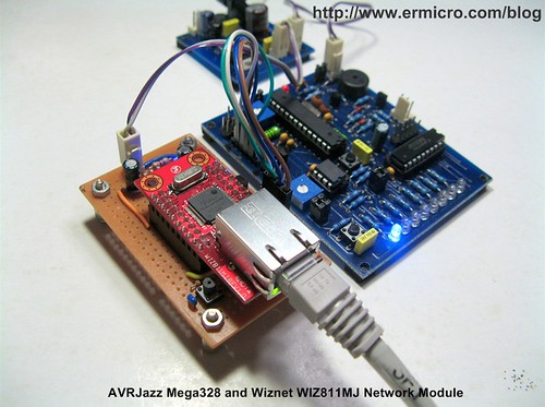
- AVRJazz Mega328 board and JazzMate 5 Volt voltage regulator board from ermicro
- Wiznet WIZ811MJ Network Module
- Atmel AVR Studio version 4.17 IDE
- WinAVR AVR-GCC 4.3.2; avr-libc 1.6.6 (WinAVR 20090313)
- Reference Document: W5100 Datasheet, WIZ811MJ Datasheet, W5100 Porting Guide, Atmel AVR ATMega328 Datasheet.

The Wiznet W5100 Hardwired TCP/IP Protocol Chip
Basically the Wiznet W5100 implements a full-featured of standard IEEE 802.3 (Ethernet physical and data link layer) and powerful TCP/IP stack inside the chip; this make the Wiznet W5100 chip is suitable choice for integrating the embedded system into the internet. Programming the Wiznet W5100 chip is also easier as we just need to write and read to and from the W5100 internal registers in order to use the build-in TCP/IP protocol features.

The Wiznet W5100 chip come with three method of controlling its internal registers; this first two is to use the parallel direct or indirect bus, the last one is to use a well known embedded serial data transfer known as the SPI (serial peripheral interface), on this tutorial we are going to use the SPI to control the Wiznet W5100 chip. You could read more about SPI on my previous posted blog Using Serial Peripheral Interface (SPI) Master and Slave with Atmel AVR Microcontroller. The basic SPI connection between the Wiznet WIZ811MJ network module and Atmel AVR ATMega328 microcontroller is shown on this following picture.

The Wiznet W5100 will act as the SPI slave device controlled by Atmel AVR ATMega328 microcontroller as the SPI Master. The SPI protocol need at least four signal i.e. MOSI (Master Out Serial In), MISO (Master In Serial Out), SCK (signal clock provided by the master) and CS (the SPI slave chip select). Although the AVR ATMega328 microcontroller support all the SPI modes (i.e. 0,1,2 and 3) but the Wiznet W5100 chip support the most SPI common modes (mode 0 and mode 3) where it will sample a data on rising edge clock and outputting on the falling edge clock. The W5100 chip also provides the interrupt pin, but on this tutorial we don’t use the interrupt feature, instead we use a pooling method to control the W5100 operation.

In order to understand of how we control the Wiznet W5100 as the SPI slave device, we are going to create the W5100 initialization program; so it will response to the simple “ping” network command (ICMP protocol). The following is the complete C code called “wiznetping.c” for initializing the Wiznet W5100 chip.
/*****************************************************************************
//  File Name    : wiznetping.c
//  Version      : 1.0
//  Description  : Wiznet W5100
//  Author       : RWB
//  Target       : AVRJazz Mega168 Board
//  Compiler     : AVR-GCC 4.3.2; avr-libc 1.6.6 (WinAVR 20090313)
//  IDE          : Atmel AVR Studio 4.17
//  Programmer   : AVRJazz Mega168 STK500 v2.0 Bootloader
//               : AVR Visual Studio 4.17, STK500 programmer
//  Last Updated : 01 July 2010
*****************************************************************************/
#include <avr/io.h>
#include <string.h>
#include <stdio.h>
#include <util/delay.h>

#define BAUD_RATE 19200
// AVRJazz Mega168/328 SPI I/O
#define SPI_PORT PORTB
#define SPI_DDR  DDRB
#define SPI_CS   PORTB2
// Wiznet W5100 Op Code
#define WIZNET_WRITE_OPCODE 0xF0
#define WIZNET_READ_OPCODE 0x0F
// Wiznet W5100 Register Addresses
#define MR   0x0000   // Mode Register
#define GAR  0x0001   // Gateway Address: 0x0001 to 0x0004
#define SUBR 0x0005   // Subnet mask Address: 0x0005 to 0x0008
#define SAR  0x0009   // Source Hardware Address (MAC): 0x0009 to 0x000E
#define SIPR 0x000F   // Source IP Address: 0x000F to 0x0012
#define RMSR 0x001A   // RX Memory Size Register
#define TMSR 0x001B   // TX Memory Size Register
void uart_init(void)
{
  UBRR0H = (((F_CPU/BAUD_RATE)/16)-1)>>8;	// set baud rate
  UBRR0L = (((F_CPU/BAUD_RATE)/16)-1);
  UCSR0B = (1<<RXEN0)|(1<<TXEN0); 		// enable Rx & Tx
  UCSR0C=  (1<<UCSZ01)|(1<<UCSZ00);  	       // config USART; 8N1
}
void uart_flush(void)
{
  unsigned char dummy;
  while (UCSR0A & (1<<RXC0)) dummy = UDR0;
}
int uart_putch(char ch,FILE *stream)
{
   if (ch == '\n')
    uart_putch('\r', stream);
   while (!(UCSR0A & (1<<UDRE0)));
   UDR0=ch;
   return 0;
}
int uart_getch(FILE *stream)
{
   unsigned char ch;
   while (!(UCSR0A & (1<<RXC0)));
   ch=UDR0;

   /* Echo the Output Back to terminal */
   uart_putch(ch,stream);

   return ch;
}
void ansi_cl(void)
{
  // ANSI clear screen: cl=\E[H\E[J
  putchar(27);
  putchar('[');
  putchar('H');
  putchar(27);
  putchar('[');
  putchar('J');
}
void ansi_me(void)
{
  // ANSI turn off all attribute: me=\E[0m
  putchar(27);
  putchar('[');
  putchar('0');
  putchar('m');
}
void SPI_Write(unsigned int addr,unsigned char data)
{
  // Activate the CS pin
  SPI_PORT &= ~(1<<SPI_CS);
  // Start Wiznet W5100 Write OpCode transmission
  SPDR = WIZNET_WRITE_OPCODE;
  // Wait for transmission complete
  while(!(SPSR & (1<<SPIF)));
  // Start Wiznet W5100 Address High Bytes transmission
  SPDR = (addr & 0xFF00) >> 8;
  // Wait for transmission complete
  while(!(SPSR & (1<<SPIF)));
  // Start Wiznet W5100 Address Low Bytes transmission
  SPDR = addr & 0x00FF;
  // Wait for transmission complete
  while(!(SPSR & (1<<SPIF)));

  // Start Data transmission
  SPDR = data;
  // Wait for transmission complete
  while(!(SPSR & (1<<SPIF)));
  // CS pin is not active
  SPI_PORT |= (1<<SPI_CS);
}
unsigned char SPI_Read(unsigned int addr)
{
  // Activate the CS pin
  SPI_PORT &= ~(1<<SPI_CS);
  // Start Wiznet W5100 Read OpCode transmission
  SPDR = WIZNET_READ_OPCODE;
  // Wait for transmission complete
  while(!(SPSR & (1<<SPIF)));
  // Start Wiznet W5100 Address High Bytes transmission
  SPDR = (addr & 0xFF00) >> 8;
  // Wait for transmission complete
  while(!(SPSR & (1<<SPIF)));
  // Start Wiznet W5100 Address Low Bytes transmission
  SPDR = addr & 0x00FF;
  // Wait for transmission complete
  while(!(SPSR & (1<<SPIF)));

  // Send Dummy transmission for reading the data
  SPDR = 0x00;
  // Wait for transmission complete
  while(!(SPSR & (1<<SPIF)));

  // CS pin is not active
  SPI_PORT |= (1<<SPI_CS);
  return(SPDR);
}
void W5100_Init(void)
{
  // Ethernet Setup
  unsigned char mac_addr[] = {0x00,0x16,0x36,0xDE,0x58,0xF6};
  unsigned char ip_addr[] = {192,168,2,10};
  unsigned char sub_mask[] = {255,255,255,0};
  unsigned char gtw_addr[] = {192,168,2,1};
  // Setting the Wiznet W5100 Mode Register: 0x0000
  SPI_Write(MR,0x80);            // MR = 0b10000000;
  _delay_ms(1);
  printf("Reading MR: %d\n\n",SPI_Read(MR));
  // Setting the Wiznet W5100 Gateway Address (GAR): 0x0001 to 0x0004
  printf("Setting Gateway Address %d.%d.%d.%d\n",gtw_addr[0],gtw_addr[1],\
          gtw_addr[2],gtw_addr[3]);
  SPI_Write(GAR + 0,gtw_addr[0]);
  SPI_Write(GAR + 1,gtw_addr[1]);
  SPI_Write(GAR + 2,gtw_addr[2]);
  SPI_Write(GAR + 3,gtw_addr[3]);
  _delay_ms(1);
  printf("Reading GAR: %d.%d.%d.%d\n\n",SPI_Read(GAR + 0),SPI_Read(GAR + 1),\
          SPI_Read(GAR + 2),SPI_Read(GAR + 3));
  // Setting the Wiznet W5100 Source Address Register (SAR): 0x0009 to 0x000E
  printf("Setting Source Address %.2x:%.2x:%.2x:%.2x:%.2x:%.2x\n",mac_addr[0],mac_addr[1],\
          mac_addr[2],mac_addr[3],mac_addr[4],mac_addr[5]);
  SPI_Write(SAR + 0,mac_addr[0]);
  SPI_Write(SAR + 1,mac_addr[1]);
  SPI_Write(SAR + 2,mac_addr[2]);
  SPI_Write(SAR + 3,mac_addr[3]);
  SPI_Write(SAR + 4,mac_addr[4]);
  SPI_Write(SAR + 5,mac_addr[5]);
  _delay_ms(1);
  printf("Reading SAR: %.2x:%.2x:%.2x:%.2x:%.2x:%.2x\n\n",SPI_Read(SAR + 0),SPI_Read(SAR + 1),\
          SPI_Read(SAR + 2),SPI_Read(SAR + 3),SPI_Read(SAR + 4),SPI_Read(SAR + 5));
  // Setting the Wiznet W5100 Sub Mask Address (SUBR): 0x0005 to 0x0008
  printf("Setting Sub Mask Address %d.%d.%d.%d\n",sub_mask[0],sub_mask[1],\
          sub_mask[2],sub_mask[3]);
  SPI_Write(SUBR + 0,sub_mask[0]);
  SPI_Write(SUBR + 1,sub_mask[1]);
  SPI_Write(SUBR + 2,sub_mask[2]);
  SPI_Write(SUBR + 3,sub_mask[3]);
  _delay_ms(1);
  printf("Reading SUBR: %d.%d.%d.%d\n\n",SPI_Read(SUBR + 0),SPI_Read(SUBR + 1),\
          SPI_Read(SUBR + 2),SPI_Read(SUBR + 3));
  // Setting the Wiznet W5100 IP Address (SIPR): 0x000F to 0x0012
  printf("Setting IP Address %d.%d.%d.%d\n",ip_addr[0],ip_addr[1],\
          ip_addr[2],ip_addr[3]);
  SPI_Write(SIPR + 0,ip_addr[0]);
  SPI_Write(SIPR + 1,ip_addr[1]);
  SPI_Write(SIPR + 2,ip_addr[2]);
  SPI_Write(SIPR + 3,ip_addr[3]);
  _delay_ms(1);
  printf("Reading SIPR: %d.%d.%d.%d\n\n",SPI_Read(SIPR + 0),SPI_Read(SIPR + 1),\
          SPI_Read(SIPR + 2),SPI_Read(SIPR + 3));

  // Setting the Wiznet W5100 RX and TX Memory Size, we use 2KB for Rx/Tx 4 channels
  printf("Setting Wiznet RMSR and TMSR\n\n");
  SPI_Write(RMSR,0x55);
  SPI_Write(TMSR,0x55);
  printf("Done Wiznet W5100 Initialized!\n");
}
// Assign I/O stream to UART
FILE uart_str = FDEV_SETUP_STREAM(uart_putch, uart_getch, _FDEV_SETUP_RW);
int main(void){
  // Set the PORTD as Output:
  DDRD=0xFF;
  PORTD=0x00;
   // Define Output/Input Stream
  stdout = stdin = &uart_str;
  // Initial UART Peripheral
  uart_init();
  // Clear Screen
  ansi_me();
  ansi_cl();
  ansi_me();
  ansi_cl();
  uart_flush();
  // Initial the AVR ATMega168/328 SPI Peripheral
  // Set MOSI (PORTB3),SCK (PORTB5) and PORTB2 (SS) as output, others as input
  SPI_DDR = (1<<PORTB3)|(1<<PORTB5)|(1<<PORTB2);
  // CS pin is not active
  SPI_PORT |= (1<<SPI_CS);
  // Enable SPI, Master Mode 0, set the clock rate fck/2
  SPCR = (1<<SPE)|(1<<MSTR);
  SPSR |= (1<<SPI2X);
  // Initial the Wiznet W5100
  printf("Wiznet W5100 Init\n\n");
  W5100_Init();
  // Loop forever
  for(;;){
  }
  return 0;
}
/* EOF: wiznetping.c */
After compiling and downloading the HEX program into the AVRJazz Mega328 board; connect the RJ45 connector UTP ethernet cable to your hubs/switch or you could connect directly with the cross configuration cable to your computer. Use the serial terminal such as Hyperterminal, puTTY or Tera Term and configure it to accept the serial connection with 19200 baud rate, 8-bit data with No Parity Check.
Now you are ready to test your first embedded Ethernet by using the “ping” command as shown on these following pictures:


Wiznet W5100 SPI Initialization
To initialize the W5100 chip, we need to write on each of the W5100 common registers named MR (Mode Register), SUBR (Subnet mask Register), SAR (Source Hardware Register), SIPR (Source IP Register), RMSR (Receive Memory Size Register) and TMSR (Transmit Memory Size Register).

All the Wiznet W5100 registers address has 16-bits wide and the register it self is 8-bits wide; because we use 8-bit AVR ATMega328 microcontroller SPI, therefore in order to perform write or read operation we need to pass the first 8-bit MSB (most significant byte) and follow by the 8-bit LSB (least significant byte) of the W5100 register address. The Wiznet W5100 also use two operant commands to differentiate between the WRITE (0xF0) and READ (0x0F) operation. The Wiznet W5100 SPI write and read routine is implemented in the SPI_Write() and SPI_Read() functions on the above C code.
The SAR registers is also known as the MAC (Media Access Control) address, this W5100 register will represent the unique hardware identification in the network. The MAC address is assigned and managed by Institute of Electrical and Electronics Engineers (IEEE) for each NIC (Network Interface Card) manufacturer where the first 3 bytes of 6 bytes MAC address is used to identify the organization that issued the identifier and are known as the OUI (Organizationally Unique Identifier). For example the following are the list of Atmel, Microchip and Wiznet OUI:
00-04-25   (hex)      Atmel Corporation
000425     (base 16)  Atmel Corporation
                      Multimedia & Communications Group
                      2200 Gateway Centre, Suite 201
                      Morrisville NC 27560
                      UNITED STATES
00-04-A3   (hex)      Microchip Technology, Inc.
0004A3     (base 16)  Microchip Technology, Inc.
                      2355 W. Chandler Blvd.
                      Chandler AZ 85224
                      UNITED STATES
00-08-DC   (hex)      Wiznet
0008DC     (base 16)  Wiznet
                      5F Simmtech bldg., 228-3,
                      Nonyhun, Kangnam
                      Seoul  135-830
                      KOREA, REPUBLIC OF
Now the question is how you could get your own MAC address because the Wiznet W5100 chip is shipped without its own MAC address; the answer is you could either register your own MAC address (OUI) to IEEE (of course this is not recommended for the hobbyist as this will be very expensive unless you could effort it) or you could simply use your own computer NIC’s MAC address and just change the last byte of the 6 byte MAC address and cross you finger, hopping this MAC address will be unique within your network as I did. By using the “ipconfig /all” command in the window command prompt, you could get the information of your computer MAC address in hex notation i.e. 00-16-36-DE-58-F5 (the MAC address of my computer); now by adding one to the last byte you will get the W5100 MAC address that I used in this tutorial (00-16-36-DE-58-F6).
The Wiznet W5100 support up to four simultaneous channels or sockets, each of the channels has its own registers address to control the operation. All of these channels is supported by 8 KB memory of the transmit buffer and 8 KB memory of the receive buffer. We could adjust this memory size on each channel by assigning the RMSR and TMSR register (the default is 2 KB for each channel) as shown on this following C code:
  // Setting the Wiznet W5100 RX and TX Memory Size, we use 2KB for Rx/Tx 4 channels
  printf("Setting Wiznet RMSR and TMSR\n\n");
  SPI_Write(RMSR,0x55);
  SPI_Write(TMSR,0x55);
All the W5100 initialization routine is implemented in W5100_Init() function, where we perform both writing and reading in order to understand how we could control the W5100 register through the SPI. The following is the summary of how we initialized the W5100 register. For the complete information about the W5100 registers please refer to the Wiznet W5100 datasheet (consider it as your best friend in this tutorial):
- Write 0x80 to W5100 MR (Mode Register) on address: 0x0000 to soft reset the chip
- Assign four bytes of the gateway IP address to the W5100 GAR (Gateway Address Register) on address 0x0001 to 0x0004
- Assign four bytes of the sub mask address to the W5100 SUBR (Sub Mask Address Register) on address 0x0005 to 0x0008
- Assign six bytes of the MAC address to the W5100 SAR (Source Address Register) on address 0x0009 to 0x000E
- Assign four bytes of the IP address to the W5100 SIPR (Source IP Register) on address 0x000F to 0x0012
- The last is to allocate the transmit and receive buffer size to each of RMSR (RX Memory Size Register) address: 0x001A and TMSR (TX Memory Size Register) on address 0x001B.
- Because we use the default value 0x07D0 (200 ms, where 1 mean 100 us) of the RTR (Retry Time Value Register) and default value 0x08 (8 times retry before generating interrupt) of the RCR (Retry Count Register), therefore we don’t need to set these registers
After performing all the W5100 required initialization routine you could examine whether it work or not by sending the “ping” command to the W5100 build in ICMP (Internet Control Message Protocol) package responder. If everything works, then you will get the ICMP reply from the Wiznet W5100 chip. With this understanding now we are ready to continue this tutorial and make our first simple embedded web server.
The Embedded Web Server
The advantage of using the Hypertext Transfer Protocol (HTTP) server in the embedded system is; you don’t have to develop a special client application to communicate with your embedded system. All you need is to use any standard browser that comes with your personal computer operating system or gadget to talk to your embedded system. The HTTP server uses a simple text called Hypertext Markup Language (HTML) to interact with the browser (client application) through the TCP/IP protocol.

The HTTP server work by listening to any request from the client (browser) for any HTTP “GET” or “POST” request through the TCP/IP port 80 (standard HTTP server port). Once the client sends this request to the HTTP server, then the HTTP server will response to this client request by sending the HTTP response header (HTTP/1.0 200 OK and Content-Type: text/html) follow by the blank line and the HTML text to the client, after transfer all the HTML text to the client; the HTTP server will automatically disconnect the established connection with the client. The following is the example of the client request and the HTML text response transmitted by the embedded HTTP server:
Client Request:
GET / HTTP/1.1
Host: 192.168.2.101
User-Agent: Mozilla/5.0 (Windows; U; Windows NT 5.1; en-US; rv:1.9.2.3) Gecko/20
100401 Firefox/3.6.3
Accept: text/html,application/xhtml+xml,application/xml;q=0.9,*/*;q=0.8
Accept-Language: en-us,en;q=0.5
Accept-Encoding: gzip,deflate
Accept-Charset: ISO-8859-1,utf-8;q=0.7,*;q=0.7
Keep-Alive: 115
Connection: keep-alive
HTTP Server Response:
HTTP/1.0 200 OK
Content-Type: text/html
<html>
<body>
<span style="color:#0000A0">
<h1>Embedded Web Server</h1>
<h3>AVRJazz Mega328 and WIZ811MJ</h3>
<p><form method="POST">
<strong>Temp: <input type="text" size=2 value="26"> <sup>O</sup>C
<p><input type="radio" name="radio" value="0" >Blinking LED
<br><input type="radio" name="radio" value="1" checked>Scanning LED
</strong><p>
<input type="submit">
</form></span>
</body>
</html>
The client then will translate this received HTML text and display the information on the browser screen such as room’s temperature and the output LED status. By submitting different LED setting from the browser (POST request) to the HTTP server, now we could easily give the needed instruction to the AVR ATMega328 microcontroller that also functioned as the embedded web server.
Now as you understand the basic principal of how the HTTP server protocol work, its time to implement it on the AVR ATMega328 Microcontroller and Wiznet W5100 chip. The following is the complete C code called “wiznetweb.c” for our embedded web server:
/*****************************************************************************
//  File Name    : wiznetweb.c
//  Version      : 1.0
//  Description  : AVRJazz Mega328 and Wiznet W5100 Web Server
//  Author       : RWB
//  Target       : AVRJazz Mega328 Board
//  Compiler     : AVR-GCC 4.3.2; avr-libc 1.6.6 (WinAVR 20090313)
//  IDE          : Atmel AVR Studio 4.17
//  Programmer   : AVRJazz Mega328 STK500 v2.0 Bootloader
//               : AVR Visual Studio 4.17, STK500 programmer
//  Last Updated : 20 July 2010
*****************************************************************************/
#include <avr/io.h>
#include <string.h>
#include <stdio.h>
#include <util/delay.h>
#include <avr/interrupt.h>
#include <avr/pgmspace.h>
// AVRJazz Mega328 SPI I/O
#define SPI_PORT PORTB
#define SPI_DDR  DDRB
#define SPI_CS   PORTB2
// Wiznet W5100 Op Code
#define WIZNET_WRITE_OPCODE 0xF0
#define WIZNET_READ_OPCODE 0x0F
// Wiznet W5100 Register Addresses
#define MR         0x0000      // Mode Register
#define GAR        0x0001      // Gateway Address: 0x0001 to 0x0004
#define SUBR       0x0005      // Subnet mask Address: 0x0005 to 0x0008
#define SAR        0x0009      // Source Hardware Address (MAC): 0x0009 to 0x000E
#define SIPR       0x000F      // Source IP Address: 0x000F to 0x0012
#define RMSR       0x001A      // RX Memory Size Register
#define TMSR       0x001B      // TX Memory Size Register
#define S0_MR	   0x0400      // Socket 0: Mode Register Address
#define S0_CR	   0x0401      // Socket 0: Command Register Address
#define S0_IR	   0x0402      // Socket 0: Interrupt Register Address
#define S0_SR	   0x0403      // Socket 0: Status Register Address
#define S0_PORT    0x0404      // Socket 0: Source Port: 0x0404 to 0x0405
#define SO_TX_FSR  0x0420      // Socket 0: Tx Free Size Register: 0x0420 to 0x0421
#define S0_TX_RD   0x0422      // Socket 0: Tx Read Pointer Register: 0x0422 to 0x0423
#define S0_TX_WR   0x0424      // Socket 0: Tx Write Pointer Register: 0x0424 to 0x0425
#define S0_RX_RSR  0x0426      // Socket 0: Rx Received Size Pointer Register: 0x0425 to 0x0427
#define S0_RX_RD   0x0428      // Socket 0: Rx Read Pointer: 0x0428 to 0x0429
#define TXBUFADDR  0x4000      // W5100 Send Buffer Base Address
#define RXBUFADDR  0x6000      // W5100 Read Buffer Base Address
// S0_MR values
#define MR_CLOSE	  0x00    // Unused socket
#define MR_TCP		  0x01    // TCP
#define MR_UDP		  0x02    // UDP
#define MR_IPRAW	  0x03	  // IP LAYER RAW SOCK
#define MR_MACRAW	  0x04	  // MAC LAYER RAW SOCK
#define MR_PPPOE	  0x05	  // PPPoE
#define MR_ND		  0x20	  // No Delayed Ack(TCP) flag
#define MR_MULTI	  0x80	  // support multicating
// S0_CR values
#define CR_OPEN          0x01	  // Initialize or open socket
#define CR_LISTEN        0x02	  // Wait connection request in tcp mode(Server mode)
#define CR_CONNECT       0x04	  // Send connection request in tcp mode(Client mode)
#define CR_DISCON        0x08	  // Send closing reqeuset in tcp mode
#define CR_CLOSE         0x10	  // Close socket
#define CR_SEND          0x20	  // Update Tx memory pointer and send data
#define CR_SEND_MAC      0x21	  // Send data with MAC address, so without ARP process
#define CR_SEND_KEEP     0x22	  // Send keep alive message
#define CR_RECV          0x40	  // Update Rx memory buffer pointer and receive data
// S0_SR values
#define SOCK_CLOSED      0x00     // Closed
#define SOCK_INIT        0x13	  // Init state
#define SOCK_LISTEN      0x14	  // Listen state
#define SOCK_SYNSENT     0x15	  // Connection state
#define SOCK_SYNRECV     0x16	  // Connection state
#define SOCK_ESTABLISHED 0x17	  // Success to connect
#define SOCK_FIN_WAIT    0x18	  // Closing state
#define SOCK_CLOSING     0x1A	  // Closing state
#define SOCK_TIME_WAIT	 0x1B	  // Closing state
#define SOCK_CLOSE_WAIT  0x1C	  // Closing state
#define SOCK_LAST_ACK    0x1D	  // Closing state
#define SOCK_UDP         0x22	  // UDP socket
#define SOCK_IPRAW       0x32	  // IP raw mode socket
#define SOCK_MACRAW      0x42	  // MAC raw mode socket
#define SOCK_PPPOE       0x5F	  // PPPOE socket
#define TX_BUF_MASK      0x07FF   // Tx 2K Buffer Mask:
#define RX_BUF_MASK      0x07FF   // Rx 2K Buffer Mask:
#define NET_MEMALLOC     0x05     // Use 2K of Tx/Rx Buffer
#define TCP_PORT 80 // TCP/IP Port
// Debugging Mode, 0 - Debug OFF, 1 - Debug ON
#define _DEBUG_MODE      0
#if _DEBUG_MODE
  #define BAUD_RATE 19200
#endif
// Define W5100 Socket Register and Variables Used
uint8_t sockreg;
#define MAX_BUF 512
uint8_t buf[MAX_BUF];
int tempvalue;
uint8_t ledmode,ledeye,ledsign;
#if _DEBUG_MODE
void uart_init(void)
{
  UBRR0H = (((F_CPU/BAUD_RATE)/16)-1)>>8;		// set baud rate
  UBRR0L = (((F_CPU/BAUD_RATE)/16)-1);
  UCSR0B = (1<<RXEN0)|(1<<TXEN0); 				// enable Rx & Tx
  UCSR0C=  (1<<UCSZ01)|(1<<UCSZ00);  	        // config USART; 8N1
}
void uart_flush(void)
{
  unsigned char dummy;
  while (UCSR0A & (1<<RXC0)) dummy = UDR0;
}
int uart_putch(char ch,FILE *stream)
{
   if (ch == '\n')
    uart_putch('\r', stream);
   while (!(UCSR0A & (1<<UDRE0)));
   UDR0=ch;
   return 0;
}
int uart_getch(FILE *stream)
{
   unsigned char ch;
   while (!(UCSR0A & (1<<RXC0)));
   ch=UDR0;

   /* Echo the Output Back to terminal */
   uart_putch(ch,stream);

   return ch;
}
void ansi_cl(void)
{
  // ANSI clear screen: cl=\E[H\E[J
  putchar(27);
  putchar('[');
  putchar('H');
  putchar(27);
  putchar('[');
  putchar('J');
}
void ansi_me(void)
{
  // ANSI turn off all attribute: me=\E[0m
  putchar(27);
  putchar('[');
  putchar('0');
  putchar('m');
}
#endif
void SPI_Write(uint16_t addr,uint8_t data)
{
  // Activate the CS pin
  SPI_PORT &= ~(1<<SPI_CS);
  // Start Wiznet W5100 Write OpCode transmission
  SPDR = WIZNET_WRITE_OPCODE;
  // Wait for transmission complete
  while(!(SPSR & (1<<SPIF)));
  // Start Wiznet W5100 Address High Bytes transmission
  SPDR = (addr & 0xFF00) >> 8;
  // Wait for transmission complete
  while(!(SPSR & (1<<SPIF)));
  // Start Wiznet W5100 Address Low Bytes transmission
  SPDR = addr & 0x00FF;
  // Wait for transmission complete
  while(!(SPSR & (1<<SPIF)));

  // Start Data transmission
  SPDR = data;
  // Wait for transmission complete
  while(!(SPSR & (1<<SPIF)));
  // CS pin is not active
  SPI_PORT |= (1<<SPI_CS);
}
unsigned char SPI_Read(uint16_t addr)
{
  // Activate the CS pin
  SPI_PORT &= ~(1<<SPI_CS);
  // Start Wiznet W5100 Read OpCode transmission
  SPDR = WIZNET_READ_OPCODE;
  // Wait for transmission complete
  while(!(SPSR & (1<<SPIF)));
  // Start Wiznet W5100 Address High Bytes transmission
  SPDR = (addr & 0xFF00) >> 8;
  // Wait for transmission complete
  while(!(SPSR & (1<<SPIF)));
  // Start Wiznet W5100 Address Low Bytes transmission
  SPDR = addr & 0x00FF;
  // Wait for transmission complete
  while(!(SPSR & (1<<SPIF)));

  // Send Dummy transmission for reading the data
  SPDR = 0x00;
  // Wait for transmission complete
  while(!(SPSR & (1<<SPIF)));

  // CS pin is not active
  SPI_PORT |= (1<<SPI_CS);
  return(SPDR);
}
void W5100_Init(void)
{
  // Ethernet Setup
  unsigned char mac_addr[] = {0x00,0x16,0x36,0xDE,0x58,0xF6};
  unsigned char ip_addr[] = {192,168,2,10};
  unsigned char sub_mask[] = {255,255,255,0};
  unsigned char gtw_addr[] = {192,168,2,1};
  // Setting the Wiznet W5100 Mode Register: 0x0000
  SPI_Write(MR,0x80);            // MR = 0b10000000;
  // Setting the Wiznet W5100 Gateway Address (GAR): 0x0001 to 0x0004
  SPI_Write(GAR + 0,gtw_addr[0]);
  SPI_Write(GAR + 1,gtw_addr[1]);
  SPI_Write(GAR + 2,gtw_addr[2]);
  SPI_Write(GAR + 3,gtw_addr[3]);
  // Setting the Wiznet W5100 Source Address Register (SAR): 0x0009 to 0x000E
  SPI_Write(SAR + 0,mac_addr[0]);
  SPI_Write(SAR + 1,mac_addr[1]);
  SPI_Write(SAR + 2,mac_addr[2]);
  SPI_Write(SAR + 3,mac_addr[3]);
  SPI_Write(SAR + 4,mac_addr[4]);
  SPI_Write(SAR + 5,mac_addr[5]);
  // Setting the Wiznet W5100 Sub Mask Address (SUBR): 0x0005 to 0x0008
  SPI_Write(SUBR + 0,sub_mask[0]);
  SPI_Write(SUBR + 1,sub_mask[1]);
  SPI_Write(SUBR + 2,sub_mask[2]);
  SPI_Write(SUBR + 3,sub_mask[3]);
  // Setting the Wiznet W5100 IP Address (SIPR): 0x000F to 0x0012
  SPI_Write(SIPR + 0,ip_addr[0]);
  SPI_Write(SIPR + 1,ip_addr[1]);
  SPI_Write(SIPR + 2,ip_addr[2]);
  SPI_Write(SIPR + 3,ip_addr[3]);

  // Setting the Wiznet W5100 RX and TX Memory Size (2KB),
  SPI_Write(RMSR,NET_MEMALLOC);
  SPI_Write(TMSR,NET_MEMALLOC);
}
void close(uint8_t sock)
{
   if (sock != 0) return;

   // Send Close Command
   SPI_Write(S0_CR,CR_CLOSE);
   // Waiting until the S0_CR is clear
   while(SPI_Read(S0_CR));
}
void disconnect(uint8_t sock)
{
   if (sock != 0) return;
   // Send Disconnect Command
   SPI_Write(S0_CR,CR_DISCON);
   // Wait for Disconecting Process
   while(SPI_Read(S0_CR));
}
uint8_t socket(uint8_t sock,uint8_t eth_protocol,uint16_t tcp_port)
{
    uint8_t retval=0;
    if (sock != 0) return retval;

    // Make sure we close the socket first
    if (SPI_Read(S0_SR) == SOCK_CLOSED) {
      close(sock);
    }
    // Assigned Socket 0 Mode Register
    SPI_Write(S0_MR,eth_protocol);

    // Now open the Socket 0
    SPI_Write(S0_PORT,((tcp_port & 0xFF00) >> 8 ));
    SPI_Write(S0_PORT + 1,(tcp_port & 0x00FF));
    SPI_Write(S0_CR,CR_OPEN);                   // Open Socket
    // Wait for Opening Process
    while(SPI_Read(S0_CR));
    // Check for Init Status
    if (SPI_Read(S0_SR) == SOCK_INIT)
      retval=1;
    else
      close(sock);

    return retval;
}
uint8_t listen(uint8_t sock)
{
   uint8_t retval = 0;
if (sock != 0) return retval;
   if (SPI_Read(S0_SR) == SOCK_INIT) {
     // Send the LISTEN Command
     SPI_Write(S0_CR,CR_LISTEN);

     // Wait for Listening Process
     while(SPI_Read(S0_CR));
     // Check for Listen Status
     if (SPI_Read(S0_SR) == SOCK_LISTEN)
       retval=1;
     else
       close(sock);
    }
    return retval;
}
uint16_t send(uint8_t sock,const uint8_t *buf,uint16_t buflen)
{
    uint16_t ptr,offaddr,realaddr,txsize,timeout;

    if (buflen <= 0 || sock != 0) return 0;
#if _DEBUG_MODE
    printf("Send Size: %d\n",buflen);
#endif
    // Make sure the TX Free Size Register is available
    txsize=SPI_Read(SO_TX_FSR);
    txsize=(((txsize & 0x00FF) << 8 ) + SPI_Read(SO_TX_FSR + 1));
#if _DEBUG_MODE
    printf("TX Free Size: %d\n",txsize);
#endif
    timeout=0;
    while (txsize < buflen) {
      _delay_ms(1);
     txsize=SPI_Read(SO_TX_FSR);
     txsize=(((txsize & 0x00FF) << 8 ) + SPI_Read(SO_TX_FSR + 1));
     // Timeout for approx 1000 ms
     if (timeout++ > 1000) {
#if _DEBUG_MODE
       printf("TX Free Size Error!\n");
#endif
       // Disconnect the connection
       disconnect(sock);
       return 0;
     }
   }

   // Read the Tx Write Pointer
   ptr = SPI_Read(S0_TX_WR);
   offaddr = (((ptr & 0x00FF) << 8 ) + SPI_Read(S0_TX_WR + 1));
#if _DEBUG_MODE
    printf("TX Buffer: %x\n",offaddr);
#endif

    while(buflen) {
      buflen--;
      // Calculate the real W5100 physical Tx Buffer Address
      realaddr = TXBUFADDR + (offaddr & TX_BUF_MASK);
      // Copy the application data to the W5100 Tx Buffer
      SPI_Write(realaddr,*buf);
      offaddr++;
      buf++;
    }

    // Increase the S0_TX_WR value, so it point to the next transmit
    SPI_Write(S0_TX_WR,(offaddr & 0xFF00) >> 8 );
    SPI_Write(S0_TX_WR + 1,(offaddr & 0x00FF));

    // Now Send the SEND command
    SPI_Write(S0_CR,CR_SEND);

    // Wait for Sending Process
    while(SPI_Read(S0_CR));

    return 1;
}
uint16_t recv(uint8_t sock,uint8_t *buf,uint16_t buflen)
{
    uint16_t ptr,offaddr,realaddr;

    if (buflen <= 0 || sock != 0) return 1;

    // If the request size > MAX_BUF,just truncate it
    if (buflen > MAX_BUF)
      buflen=MAX_BUF - 2;
    // Read the Rx Read Pointer
    ptr = SPI_Read(S0_RX_RD);
    offaddr = (((ptr & 0x00FF) << 8 ) + SPI_Read(S0_RX_RD + 1));
#if _DEBUG_MODE
    printf("RX Buffer: %x\n",offaddr);
#endif

    while(buflen) {
      buflen--;
      realaddr=RXBUFADDR + (offaddr & RX_BUF_MASK);
      *buf = SPI_Read(realaddr);
      offaddr++;
      buf++;
    }
    *buf='\0';        // String terminated character

    // Increase the S0_RX_RD value, so it point to the next receive
    SPI_Write(S0_RX_RD,(offaddr & 0xFF00) >> 8 );
    SPI_Write(S0_RX_RD + 1,(offaddr & 0x00FF));

    // Now Send the RECV command
    SPI_Write(S0_CR,CR_RECV);
    _delay_us(5);    // Wait for Receive Process

    return 1;
}
uint16_t recv_size(void)
{
  return ((SPI_Read(S0_RX_RSR) & 0x00FF) << 8 ) + SPI_Read(S0_RX_RSR + 1);
}
int strindex(char *s,char *t)
{
  uint16_t i,n;

  n=strlen(t);
  for(i=0;*(s+i); i++) {
    if (strncmp(s+i,t,n) == 0)
      return i;
  }
  return -1;
}
ISR(TIMER0_OVF_vect)
{
  static unsigned char tenms=1;
  tenms++;                  // Read ADC every 20 x 10ms = 200 milisecond
  if (tenms >= 20) {
    cli();                                // Disable Interupt
    // Select the LED Mode here
    if (ledmode == 1) {
      if (ledeye <= 0) ledeye=0x01;
      if (ledsign == 0) {
	PORTD=ledeye;
	ledeye=ledeye << 1;
	if (ledeye >= 0x80) ledsign=1;
      } else {
	PORTD=ledeye;
	ledeye=ledeye >> 1;
	if (ledeye <= 0x01) ledsign=0;
      }
    } else {
      if (ledsign == 0) {
	PORTD=0x00;
	ledsign=1;
      } else {
	PORTD=0xFF;
	ledsign=0;
      }
    }
    // Set ADMUX Channel for LM35DZ Input
    ADMUX=0x01;
    // Start conversion by setting ADSC on ADCSRA Register
    ADCSRA |= (1<<ADSC);
    // wait until convertion complete ADSC=0 -> Complete
    while (ADCSRA & (1<<ADSC));
    // Get the ADC Result
    tempvalue = ADCW;
    // ADC = (Vin x 1024) / Vref, Vref = 1 Volt, LM35DZ Out = 10mv/C
    tempvalue = (int)(tempvalue) / 10.24;

    tenms=1;

    sei();                            // Enable Interupt
  }
  // Start counter from 0x94, overflow at 10 mSec
  TCNT0=0x94;
}
#if _DEBUG_MODE
// Assign I/O stream to UART
FILE uart_str = FDEV_SETUP_STREAM(uart_putch, uart_getch, _FDEV_SETUP_RW);
#endif
int main(void){
  uint8_t sockstat;
  uint16_t rsize;
  char radiostat0[10],radiostat1[10],temp[4];
  int getidx,postidx;

  // Reset Port D
  DDRD = 0xFF;       // Set PORTD as Output
  PORTD = 0x00;

#if _DEBUG_MODE
  // Define Output/Input Stream
  stdout = stdin = &uart_str;
  // Initial UART Peripheral
  uart_init();
  // Clear Screen
  ansi_me();
  ansi_cl();
  ansi_me();
  ansi_cl();
  uart_flush();
#endif
  // Initial ATMega386 ADC Peripheral
  ADCSRA = (1<<ADEN) | (1<<ADPS2) | (1<<ADPS1);
  // Free running ADC Mode
  ADCSRB = 0x00;
  // Initial the AVR ATMega328 SPI Peripheral
  // Set MOSI (PORTB3),SCK (PORTB5) and PORTB2 (SS) as output, others as input
  SPI_DDR = (1<<PORTB3)|(1<<PORTB5)|(1<<PORTB2);
  // CS pin is not active
  SPI_PORT |= (1<<SPI_CS);
  // Enable SPI, Master Mode 0, set the clock rate fck/2
  SPCR = (1<<SPE)|(1<<MSTR);
  SPSR |= (1<<SPI2X);

  // Initial ATMega368 Timer/Counter0 Peripheral
  TCCR0A=0x00;                  // Normal Timer0 Operation
  TCCR0B=(1<<CS02)|(1<<CS00);   // Use maximum prescaller: Clk/1024
  TCNT0=0x94;                   // Start counter from 0x94, overflow at 10 mSec
  TIMSK0=(1<<TOIE0);            // Enable Counter Overflow Interrupt
  sei();                        // Enable Interrupt

  // Initial the W5100 Ethernet
  W5100_Init();
  // Initial variable used
  sockreg=0;
  tempvalue=0;
  ledmode=1;
  ledeye=0x01;                  // Initial LED Eye Variables
  ledsign=0;
#if _DEBUG_MODE
  printf("WEB Server Debug Mode\n\n");
#endif

  // Loop forever
  for(;;){
    sockstat=SPI_Read(S0_SR);
    switch(sockstat) {
     case SOCK_CLOSED:
        if (socket(sockreg,MR_TCP,TCP_PORT) > 0) {
	  // Listen to Socket 0
	  if (listen(sockreg) <= 0)
	    _delay_ms(1);
#if _DEBUG_MODE
          printf("Socket Listen!\n");
#endif
	}
	break;
     case SOCK_ESTABLISHED:
	// Get the client request size
        rsize=recv_size();
#if _DEBUG_MODE
	printf("Size: %d\n",rsize);
#endif
	if (rsize > 0) {
	  // Now read the client Request
	  if (recv(sockreg,buf,rsize) <= 0) break;
#if _DEBUG_MODE
  	  printf("Content:\n%s\n",buf);
#endif
          // Check the Request Header
	  getidx=strindex((char *)buf,"GET /");
	  postidx=strindex((char *)buf,"POST /");
	  if (getidx >= 0 || postidx >= 0) {
#if _DEBUG_MODE
	    printf("Req. Check!\n");
#endif
            // Now check the Radio Button for POST request
	    if (postidx >= 0) {
	      if (strindex((char *)buf,"radio=0") > 0)
	        ledmode=0;
	      if (strindex((char *)buf,"radio=1") > 0)
	        ledmode=1;
            }
#if _DEBUG_MODE
	    printf("Req. Send!\n");
#endif
	    // Create the HTTP Response	Header
	    strcpy_P((char *)buf,PSTR("HTTP/1.0 200 OK\r\nContent-Type: text/html\r\n\r\n"));
	    strcat_P((char *)buf,PSTR("<html><body><span style=\"color:#0000A0\">\r\n"));
	    strcat_P((char *)buf,PSTR("<h1>Embedded Web Server</h1>\r\n"));
	    strcat_P((char *)buf,PSTR("<h3>AVRJazz Mega328 and WIZ811MJ</h3>\r\n"));
	    strcat_P((char *)buf,PSTR("<p><form method=\"POST\">\r\n"));
	    // Now Send the HTTP Response
	    if (send(sockreg,buf,strlen((char *)buf)) <= 0) break;

	    // Create the HTTP Temperature Response
	    sprintf((char *)temp,"%d",tempvalue);        // Convert temperature value to string
	    strcpy_P((char *)buf,PSTR("<strong>Temp: <input type=\"text\" size=2 value=\""));
	    strcat((char *)buf,temp);
	    strcat_P((char *)buf,PSTR("\"> <sup>O</sup>C\r\n"));

	    if (ledmode == 1) {
	      strcpy(radiostat0,"");
	      strcpy_P(radiostat1,PSTR("checked"));
	    } else {
	      strcpy_P(radiostat0,PSTR("checked"));
	      strcpy(radiostat1,"");
	    }
            // Create the HTTP Radio Button 0 Response
	    strcat_P((char *)buf,PSTR("<p><input type=\"radio\" name=\"radio\" value=\"0\" "));
	    strcat((char *)buf,radiostat0);
	    strcat_P((char *)buf,PSTR(">Blinking LED\r\n"));
	    strcat_P((char *)buf,PSTR("<br><input type=\"radio\" name=\"radio\" value=\"1\" "));
	    strcat((char *)buf,radiostat1);
	    strcat_P((char *)buf,PSTR(">Scanning LED\r\n"));
 	    strcat_P((char *)buf,PSTR("</strong><p>\r\n"));
	    strcat_P((char *)buf,PSTR("<input type=\"submit\">\r\n"));
	    strcat_P((char *)buf,PSTR("</form></span></body></html>\r\n"));
            // Now Send the HTTP Remaining Response
	    if (send(sockreg,buf,strlen((char *)buf)) <= 0) break;
          }
	  // Disconnect the socket
	  disconnect(sockreg);
        } else
	  _delay_us(10);    // Wait for request
break;
      case SOCK_FIN_WAIT:
      case SOCK_CLOSING:
      case SOCK_TIME_WAIT:
      case SOCK_CLOSE_WAIT:
      case SOCK_LAST_ACK:
        // Force to close the socket
	close(sockreg);
#if _DEBUG_MODE
	printf("Socket Close!\n");
#endif
	break;
    }
  }
  return 0;
}
/* EOF: wiznetweb.c */
From the C code above you’ve noticed that I used many of the Atmel AVR ATMega328 microcontroller build in peripherals features such as SPI, ADC, TIMER and the UART at the same time in order to achieve the project’s goal, you could read more information of how to use all of these peripherals on my previous posted blog Analog to Digital Converter AVR C Programming and Working with AVR microcontroller Communication Port Project.
The W5100 HTTP Server
To build the HTTP server we need to listen for the client request, read the client request and send the HTML response to the client through the TCP/IP protocol. To configure and control the Wiznet W5100 as the HTTP server basically we need to write and read to and from the Wiznet W5100 Socket Control Register and the TX and RX buffer memory; for the purpose of this tutorial (easier to understand) I only implement one channel (socket 0) of the four available channels (socket 0, 1, 2 and 3) supported by the W5100 chip. But once you understand the basic principal of how the W5100 work on this tutorial it would be easy to implement the remaining channels.
The Wiznet W5100 socket 0 control registers start at address 0x0400 to 0x04FF, the following is the list of W5100 socket 0 control registers with the 2 KB of TX and RX memory buffer used to make the HTTP server in this tutorial (again please refer to the W5100 datasheet for detail information).

Now fasten your seat belt as we are going through the code algorithm behind this W5100 HTTP server program!
Basically we use the command register (S0_CR) to instruct the W5100 chip to write or read to or from the W5100 memory buffer to make a simple HTTP server that response to the client request. The following diagram show of how we could achieve this objective:

From the diagram above after we initialized the W5100 (i.e. it could response to the “ping” command request) we continue with opening the TCP/IP port 80 and listen to this port for any client request. Assigning the TCP/IP protocol and opening the port 80 routine is implemented in the socket() function as shown on this following C code:
...
// Assigned Socket 0 Mode Register
SPI_Write(S0_MR,eth_protocol);

// Now open the Socket 0
SPI_Write(S0_PORT,((tcp_port & 0xFF00) >> 8 ));
SPI_Write(S0_PORT + 1,(tcp_port & 0x00FF));
SPI_Write(S0_CR,CR_OPEN);                   // Open Socket
// Wait for Opening Process
while(SPI_Read(S0_CR));
...
After we wrote the CR_OPEN (0x01) command on the socket 0 command register (S0_CR), then the W5100 will automatically clear this register; therefore we could take advantage of this behavior by reading this register again and examine its contents. Upon completion of the command execution process the contents of the SO_CR register will be reset to 0x00 and the socket 0 status register (S0_SR) will be set to the SOCK_INIT (0x13) status.
Listening to the opening TCP/IP port (i.e. 80) could be done by sending the CR_LISTEN (0x02) command to the socket 0 command register (S0_CR), this will change the socket 0 status register (S0_SR) to the SOCK_LISTEN (0x14) status. The listening routine is implemented in the listen() function. Now the Wiznet W5100 is ready to receive the request from client (browser).
When the client established the connection with the HTTP server, it will send the standard HTTP request protocol to the HTTP server. We could examine whether the connection has been established with the client by reading the status register (SO_CR) for SOCK_ESTABLISHED (0x17) status. Next we examine the RX receive data size by reading the socket 0 received size register (SO_RX_RSR); this routine is implemented in recv_size() function bellow:
uint16_t recv_size(void)
{
  return ((SPI_Read(S0_RX_RSR) & 0x00FF) << 8 ) + SPI_Read(S0_RX_RSR + 1);
}
If the received data exist in the RX buffer memory then we continue to read the RX memory buffer content which is implemented in recv() function. The reading process is accomplished by first calculating the received data physical address location at the 2 KB (2048 or 0x800 in hex notations) RX memory buffer boundary and then start to read the data from this location. The following picture show of how we determine the physical address of the received data.

To determine the Wiznet W5100 RX memory buffer physical address where we start to read the received data we have to mask the value returned by the socket 0 RX read pointer (S0_RX_RD) with the 0x7FF (2 KB minus one in hex notations) and add the result to the RX memory buffer base address 0x6000. Next we use this address result to retrieve the data from RX memory buffer as shown on this following C code:
...
// Read the Rx Read Pointer
ptr = SPI_Read(S0_RX_RD);
offaddr = (((ptr & 0x00FF) << 8 ) + SPI_Read(S0_RX_RD + 1));

while(buflen) {
  buflen--;
  realaddr=RXBUFADDR + (offaddr & RX_BUF_MASK);
  *buf = SPI_Read(realaddr);
  offaddr++;
  buf++;
}
*buf='\0';        // String terminated character
...
After reading all the data we need to write the last pointer value back to the socket 0 RX read pointer register (S0_RX_RD) so the W5100 RX received circular buffer mechanism will know where to put the next received data on the RX memory buffer as shown on this following C code:
...
// Increase the S0_RX_RD value, so it point to the next receive
SPI_Write(S0_RX_RD,(offaddr & 0xFF00) >> 8 );
SPI_Write(S0_RX_RD + 1,(offaddr & 0x00FF));
...
Finally we give the CR_RECV (0x40) to the W5100 socket 0 command register (S0_CR) to complete the W5100 receiving process (updating the RX memory buffer pointer and received data).
...
// Now Send the RECV command
SPI_Write(S0_CR,CR_RECV);
_delay_us(5);    // Wait for Receive Process
...
The HTTP server will send the response after examining the client request; on this tutorial the response will be the room’s temperature read by the AVR ATMega328 microcontroller ADC peripheral through the AVRJazz Mega328 on board LM35DZ temperature sensor and setting the LED display. In order to save the microcontroller RAM; all the static HTML data is stored in the flash program memory (flash RAM) use a special AVR-GCC PSTR macro and string manipulation functions such as strcpy_P() and strcat_P() to work with static string data stored in the flash program memory as shown on this following C code:
...
// Create the HTTP Response Header
strcpy_P((char *)buf,PSTR("HTTP/1.0 200 OK\r\nContent-Type: text/html\r\n\r\n"));
strcat_P((char *)buf,PSTR("<html><body><span style=\"color:#0000A0\">\r\n"));
strcat_P((char *)buf,PSTR("<h1>Embedded Web Server</h1>\r\n"));
...
After copying all the HTML response to the application buffer data (buf), now we are ready to send the response to the client. This function is implemented in the send() function. Before sending we need to check the availability of the W5100 TX memory buffer by reading the W5100 socket 0 free size register (S0_TX_FSR); on normal condition this register should return the value of 2 KB (0x0200) free. After examining this register we are ready to send data in the application buffer and use the same principal as receiving data to determine the actual TX buffer physical address as shown on this following diagram:

Similar to the read operation; to determine the Wiznet W5100 TX memory buffer physical address where we start to write the data we have to mask the value returned by the socket 0 TX write pointer (S0_TX_WR) with the 0x7FF (2 KB minus one in hex notations) and add the result to the TX memory buffer base address 0x4000. Next we use this address result to put the data to TX memory buffer as shown on this following C code:
...
// Read the Tx Write Pointer
ptr = SPI_Read(S0_TX_WR);
offaddr = (((ptr & 0x00FF) << 8 ) + SPI_Read(S0_TX_WR + 1));

while(buflen) {
  buflen--;
  // Calculate the real W5100 physical Tx Buffer Address
  realaddr = TXBUFADDR + (offaddr & TX_BUF_MASK);
  // Copy the application data to the W5100 Tx Buffer
  SPI_Write(realaddr,*buf);
  offaddr++;
  buf++;
}
...
After putting all the data to the TX memory buffer, we need to write the last pointer value back to the socket 0 TX write pointer register (S0_TX_WR) for the next TX memory buffer writing as shown on this following C code:
...
// Increase the S0_TX_WR value, so it point to the next transmit
SPI_Write(S0_TX_WR,(offaddr & 0xFF00) >> 8 );
SPI_Write(S0_TX_WR + 1,(offaddr & 0x00FF));
...
Next we need to write the CR_SEND (0x20) command to the W5100 socket 0 command register (S0_CR) to instruct the W5100 chip to send the HTML response data in the TX memory buffer.
...
// Now Send the SEND command
SPI_Write(S0_CR,CR_SEND);
...
To comply with the HTTP protocol requirement, after sending the HTML response to the client we need to disconnect and close the connection with the client. These routines are implemented in the disconnect() and close() functionsThese two functions simply send the CR_DISCON (0x08) and CR_CLOSE (0x10) to the W5100 socket 0 command register (S0_CR) respectively as shown on this following C code:
...
// Send Disconnect Command
SPI_Write(S0_CR,CR_DISCON);
...
...
// Send Close Command
SPI_Write(S0_CR,CR_CLOSE);
...
Next the infinite loop routine in main program will start opening and listening to the new client request and the whole process is repeated again.
The Temperature and LED Display Indicator
Before executing the for() infinite loop, first we initialized all the needed peripherals such as PORTD for displaying LED, UART for debugging, ADC for reading temperature sensor, SPI for communicating with the Wiznet W5100 chip and last TIMER0 for ADC conversion and controlling the LED display.
The HTTP server protocol handshaking is implemented inside the infinite loop and I use the AVR ATMega328 microcontroller TIMER0 to implement the temperature reading through the ADC peripheral and to control the LED display indicator. The AVR ATMega328 TIMER0 peripheral is being set to execute the TIMER0 interrupt routine ISR(TIMER0_OVF_vect) on every 10 ms. Using the tenms counter variable, we reduce down to about 200 ms to make the LED display appear nicely in our eyes and at the same time we do the ADC conversion from the National Semiconductor LM35DZ precision centigrade temperature sensor. You could read more about reading the LM35DZ from my previous posted blog AVR LCD Thermometer Using ADC and PWM Project.
You could easily activate the debugging mode by changing the _DEBUG_MODE definition value to 1 before compiling the program and use the serial terminal program to watch the result.
// Debugging Mode, 0 - Debug OFF, 1 - Debug ON
#define _DEBUG_MODE   1
This simple embedded Web server C code only took about 6196 bytes of the flash RAM and 816 bytes of the SRAM (debug mode turn off). The whole C code in this project is designed to be just a single file (i.e. wiznetweb.c) and all you need is the standard Win-AVR GCC includes file in order to make this program compiled successfully in the Atmel AVR Studio environment as shown on this following picture:


Now you could enjoy the embedded web server project video on this tutorial. In this video I used both acer aspire notebook and BlackBerry Javelin 8900 smart phone to access the embedded web server which is connected to the Linksys Wireless-G 2.4GHz broadband router:
The Final Thought
Actually the W5100 socket driver for the Atmel AVR microcontroller families has been provided by the Wiznet (version 1.5, as I published this blog), you could download the driver from their site (http://www.wiznet.co.kr). This driver (version 1.4) is adapted and used in the Arduino framework environment, known as the Arduino Ethernet Shield library.
Of course if I use the Wiznet socket driver in this project then you won’t learn anything, therefore to honor the spirit of experimenting inside every electronics hobbyists I decided to write my own version of the Wiznet W5100 socket driver for this project. Hopefully this project will give you a better understanding of how to integrate the Wiznet W5100 TCP/IP hardwire chip in your next embedded system application.
Bookmarks and Share


Related Posts
64 Responses to “Integrating Wiznet W5100, WIZ811MJ network module with Atmel AVR Microcontroller”
Comment by rwb.
Yes this is an original and only could be found here. Most of the ethernet C code out there use the wiznet driver or modified version of it (e.g. Arduino Ethernet Shield Library). I would be glad if you want to referencing this article in your blog.
The SD card read/write through SPI (Serial Peripheral Interface) is on my article’s queue list.
Comment by jfran.
An excellent article that I found a great help in becoming familiar with the W5100 in TCP mode. Thanks for posting this.
I have discovered something that may be a bug. When using a browser (either Google Chrome or IE) to repeatedly change the state LED state I occasionally see the radio button revert to its previous state when clicking ‘submit’. After some investigation I have discovered the following:
1. User sets one of the radio buttons in the browser then clicks submit.
2. In the main for(;;) loop a transition to SOCK_ESTABLISHED is seen and the received web page is parsed for either “radio=0” or “radio=1”.
3. Occasionally this code is executed before the entire page has been received so neither string is found.
4. The result is that the LED state is not updated and the old state gets reported back to the browser.
A rather inelegant fix is to add a delay before capturing the ‘receive size’ to allow sufficient time for the entire page to arrive.. A more elegant solution may be to re-test the ‘receive size’ if no radio button string is found and, if not 0, repeat the recv() and parsing loop.
As this is intended as a sort of tutorial perhaps changing the code is not really warranted.
Regards,
John
Comment by death_zone.
is atmega 640 board compatible as in i want to know can i implement it using atmega 640 development board
Comment by rwb.
Sure you could use the Atmel AVR ATmega640. All the Atmel AVR with SPI peripheral and at least 8K In-System Self-Programmable Flash could be used.
Comment by logist.
Excellent instructions! Thank you.
But I encountered another problem. In fact the program does not want me to show the entire HTML code in C looks like this:
// Create the HTTP Temperature Response
sprintf((char *)temp,”%d.%d”,(TempData[0]/10),(TempData[0]%10)); // Convert temperature value to string
strcpy_P((char *)buf,PSTR(“Temp[1]: OC\r\n”));
sprintf((char *)temp,”%d.%d”,(TempData[1]/10),(TempData[1]%10)); // Convert temperature value to string
strcpy_P((char *)buf,PSTR(“Temp[2]: OC\r\n”));
strcat_P((char *)buf,PSTR(“\r\n”));
// Now Send the HTTP Remaining Response
if (send(sockreg,buf,strlen((char *)buf)) <= 0) break;
I have two ds18x20 sensor that works perfectly, but my program still appears Temp [2], but I should have it written out Temp [1], temp [2] on the Web server. What is wrong in my code?
TempData [2], unsigned int size box.
Comment by rwb.
You need to “concatenate” the “temp” value to the HTML “buf” variable after assigning (sprintf command) the temperature value to the “temp” variable as shown on this following code:
strcat((char *)buf,temp);
Remember using the “strcpy” command will always overwrite the previous HTML “buf” content with a new value, while using “strcat” command will concatenate or append a new value to the existing HTML “buf” value.
Comment by logist.
Thanks, I completely forgot how it works command strcpy and strcat.
Works great.
Comment by logist.
I wonder what is better to use UDP or TCP data transfer in this case:
5 units WIZ810J and one PC (Linux server with Apache, PHP and MySQL) in the network.
But UDP has the advantage that it allows mutlicast. Server can receive data from multiple client, but the problem is that UDP does not check whether the information was successfully submitted.
As TCP checks, but does not allow multicast.
On the PC would only transmit the data measurements for the file in mysql database and then review the data.
What to me you suggest?
Comment by rwb.
Choosing whether to use UDP or TCP is depend on your application. For example when I used microcontroller and WIZ810J to control the turnstile gate connected and verified by database on the PC server I will use TCP because I need to open the turnstile gate when the barcode ticket is verified (reliability). Next when I used the same circuit for broadcasting the room’s temperature and humidity to several computers (PC) connected on the network then I will use UDP (multicast).
Comment by sam.
Hello.. Let me first start by saying that this is a great article.
I followed the code as above and when I try to ping my board it get replies only half the time. My connection doesnt seem to be reliable. What should I be looking at?
Comment by rwb.
Thanks. What did you mean by half the time? Is it slower? Try to use direct connection (cross cable) between your board and computer, make sure you use a good quality of UTP connectors and cable.
Comment by sam.
I get response for only 2 pings out of 4! I am not sure if its the cable problem or some sort of loose connection.
Comment by sam.
I was using a cross over cable and connecting it directly to my PC. I guess my PC dint like that. I am now connecting the wiznet board to a wireless router and talking to the router wirelessly from my PC. This set up works fine for me now.
Comment by pmb777.
Thank you for the exceptionally well written and documented guide! I really appreciate the single-file demonstrations, and the diagrams.
I’d like to use parts of your code in a gadget that I might sell commercially some day. Can I pay you for a license? It’d be a gesture of thanks and support.
Comment by weje.
how to connect when using the UDP protocol? example please …
Comment by rwb.
In this project we focus on TCP/IP used by the HTTP (Web Server), I will post using the UDP in the future article.
Comment by JB.
Excellent Article.
Thanks a million, going to port over for w5200 (using wiz820io) and a atm328.
JB
Comment by daniel87.
como saber si mi wiznet recibe los datos que le mando
lo que pasa es que no me ase el ping.
este es mi programa: en micro c…[truncated]
Comment by mikel.
Thanks a lot for excellent project, saved me a lots of time. I found an issue though, most of the time I got server connection reset from Firefox and always empty page from Chrome (I use Atmega328p at 4MHz). I found that after commenting some lines in your code it works well under both FF and Chrome:
//case SOCK_FIN_WAIT:
//case SOCK_CLOSING:
//case SOCK_TIME_WAIT:
case SOCK_CLOSE_WAIT:
//case SOCK_LAST_ACK:
I read W5100 documentation and there only SOCK_CLOSE_WAIT is used for socket closure in TCP IP application. Not sure why you added extra ones but it seems to cause web server resetting connection, at least in my environment.
Thanks
Michal
Comment by uraian.
In reference to the UART i need to know how you connect RS232 to the PC beacause, inside firmware list, i don’t find the setting of the PORTA-B-C-or PORTD RX-TX for send data from AVRJazz Mega328 board to the PC via RS232.
Thanks
Fulvio
Comment by rwb.
You could get the ATmega328P microcontroller UART peripheral C command in uart_init(), uart_flush(), uart_putch(), and uart_getch() functions.
Comment by uraian.
Sorry, but i don’t undestand; inside these functions there are not setting pins RX and TX of ATmega PORTs. Perhaps it is in header code of some function?
Thanks
Fulvio
Comment by rwb.
The ATmega328P microcontroller UART initiation is in uart_init() function, you should read the datasheet (see the USART part) to understand this uart_init() function. For example in order to enable the ATmega328P TXD (PD0) and RXD (PD1) for UART communication you need to set RXEN0 and TXEN0 in register UCSR0B.
Comment by uraian.
Finally i have understood.
Many Thanks.
Comment by brex305.
Nice project and it works perfectly.
Question, can this be modified to include a client that can push data to a server?
Thanks again
Comment by rwb.
You need to use the W5100 client (connect) mode instead of server (listen) mode presented in this project.
Comment by brex305.
Are there any code samples that demonstrate the use of the connect mode? I am an experienced embedded engineer but the whole ethernet/http thing is new to me. Is there reference material on the web that explains this?
Comment by rwb.
You could study the Wiznet 5100 own AVR library and the Arduino Ethernet Shield Library.
Comment by Echo.
I’d like to provide some feedback on this nice application. I wanted to introduce Ethernet to my ATmega640 system. This article has been of great help, but I encountered quite some problems.
An ATmega640 has 4 USARTs and I wanted to use USART0 in SPI mode to connect to the W5100. There are some differences between the SPI port and the USARTs. The USARTs have double buffering in their datapath. This means that you want to check on UDRE0 for when you can put the next byte in the data register UDR0. But you have to check TXC0 before manipulating CS!
Same problem when receiving; wait for TXC0 and then read UDR0 twice to be certain to obtain the response on the SPIread.
But still then, the operation was not smooth. Sometimes the whole thing hung. Obviously one of the lines like
while((UCSR0A & (1<<UDRE0)) == 0);
that used to be
while(!(SPSR & (1<<SPIF)));
never got satisfied.
It has cost me some time, but in the end I disabled the interrupts for the duration of the SPIwrite and SPIread functions and that solved it. The operation is now solid.
The next step for me is to connect a SD-card to the SPI interface and turn this into a small fileserver. However, 2GB maybe small today but it wasn't 5 years ago. Fun!
Again, thank you!
Comment by chalandi.
Thanks for posting this excellent article.
after having worked on this project I fell in the case described in the comment #3 by jfran, and the solution I’ve found is to increase the buffer size because 512 bytes is enough when using FireFox, but is not enough when using another browser.
My code example work fine with all internet browser when using a buffer of 1Kb (#define MAX_BUF 1024).
Comment by arunkumarv31.
Thanks for this excellent tutorial. I have a doubt. Instead of static IP, how can I run a dhcp client in this tutorial to obtain IP address.
Comment by rwb.
You could read the wiznet application note for DHCP implementation from their website (http://www.wiznet.co.kr).
Comment by uraian.
This project foresee a local (in house only)connection from client to web-server; can I to connect my IPhone client (i.e. in Los Angeles) to server (i.e. in NY city)connects to router modem dsl by remote connection via internet using mozilla or IE browser ? And, if yes, how to make it?
Many Thanks,
uraian
Comment by rwb.
Yes, the same setup as you connect your desktop computer to become a web server.
Comment by uraian.
Sorry, but I don’t undestand. Which setup ? Can you explain better, please ?
Thanks,
uraian.
Comment by rwb.
Basicly, first you need the public IP address, i.e. could be called from outside (internet). Next you need to configure your router to route this IP address to your local IP address used by your devices such as your microcontroller small webserver.
Comment by arunkumarv31.
I have been trying to connect to the server using socket programming in ‘C’. Below is my working scenario.
while (condition) {
connect()
send()
recv()
close()
}
Now I wanted to change this flow into
connect()
while (condition) {
send()
recv()
}
close()
For to achieve this I removed the ‘disconnect ()’ just after the send command and added that just before ‘close ()’ in ‘case SOCK_LAST_ACK:’.
Is this the correct way to have a connection till the end of the loop for to send and receive data packets.
Comment by uraian.
I have a strange question for you.
I’m trying to convert web server program from AVR ATMEGA328 to PIC, but PIC RAM (total 256 byte on gpr banks only) is insufficient and buf[MAX_BUF](512 byte) does’nt work and I can not change PIC. It’s possible to substitute RAM buffer with ROM in order send HTTP message? I think to create a ROM section array of HTTP message pointed by a variable pointer, e.g. * ptr, with the same functions of the RAM variable buf.
Many Thanks,
uraian
Comment by rwb.
@arunkumarv31: Is depend on the protocol you used, the C code project above follow the HTTP rules, where every response from the web server is followed by terminating the connection to the web client.
@uraian: Logically is possible although I’ve never used EEPROM to store dynamic data (i.e. using EEADR/EEADRH and EEADATA registers) as it not designed for this purpose. I will always choose a similar or higher specification when porting from one type of microcontroller to another, and there should be a very good reason for doing that (e.g. price, availability, and supported development tools). Anyway, my favorite 8-bit 28 pins microcontroller from Microchip is PIC18F25K22 or PIC18F26K22.
Comment by anusha.
sir, can u please give the initialization code for w5300 when 87c51 mcu and wiz830mj are used
Comment by rwb.
Currently the project is only for Wiznet W5100 (8-bit data bus, while W5300 is a 16/8-bit data bus) and Atmel AVR Microcontroller, you should check the Wiznet website for information about using the W5300.
Comment by uraian.
My card web server doesn’t connect,it does not ping with my PC, adding it doesn’t showed after ipconfig command but only PC is showed. The card and PC are connected to the router linksys WRT54G3G with LAN cable. ADSL modem is not used in this test.
May be that setup PC e/or router, TCP/IP port 80 are wrong? The actual setting of PC and router is DHCP mode (IP router and GW: 192.168.1.1,starting IP address 192.168.1.100, subnet 255.255.255.1; static IP web server: 192.168.1.102, GW 192.168.1.1, sub 255.255.255.1, MAC is the same MAC phisical of my PC but last bit modified).
Can help me ?
Many thanks.
Comment by rwb.
You could test using direct connection between the Wiznet and PC with cross UTP cable.
Comment by uraian.
Now web-server works fine with browser Firefox and I.E., but it connect only to PC connected wireless to the router, whereas my iphone, in DHCP mode, also connected wireless to router, don’t connect to web-server. Why ?
Also, web-server don’t update led status but return always old state when I submit new radio button; parsing C code in debug mode I seen that never parsed radio=0 or radio=1, but it detects fine POST or GET of the string received.
Many thanks.
Comment by rwb.
If your PC work fine, then the iPhone should work too (although I’ve never try to use the iPhone). Regarding the “radio button”, usually this is because the data is truncated, you need to increase the buf[MAX_BUF] size.
Comment by uraian.
I have created an host name in DynDNS.it and I set my router linksys in DNS mode, than I access to router from browser internet. How can I connct by internet from router to web server ?
Many Thanks.
Comment by uraian.
I Would that web-server be empowered to send e-mail to client in some cases. What C code do I need to add ?
Many thanks.
Comment by rwb.
You need to implement the email client protocol (SMTP client) to be able to sent email through the SMTP server.
Comment by slewrate.
It is a great article.Everything is explained very clearly.
Thanks for such an article.
Comment by uraian.
In reference to comment by Jfran #3, I entered this new code:
…if (postidx >= 0) {
while (strindex((char *)buf,”radio”) < 0) {
if (recv(sockreg,buf,rsize) <= 0) break;
}
#if _DEBUG_MODE
printf("buf:%s\n", buf);
#endif
………………
and web server works fine with PC(OS XP) browser Firefox, IE, and Blackberry browser. Next I have discovered an HTML bug in some browser; when I use Chrome and Iphone (rev. 4 and 5) browser, radio button value, 0 or 1, is not shown in buf register, es.: with Chrome: “buf:…radio=..q.x.o.r..” or with Iphone: “buf: …radio…e..rh…..”, so web server not works. I ask to rwb and to the other interested users if you have already experienced these cases.
Many thanks.
Comment by marco.
Thank you for this wonderful article.
I tried your code on the Arduino Ethernet board (ATMega328+w5100) with the Arduino IDE, and everything works fine (ping ok, Http ok).
Only one thing is getting me crazy; the line:
FILE uart_str = FDEV_SETUP_STREAM(uart_putch, uart_getch, _FDEV_SETUP_RW);
causes the following compile error (repeated 4 times:
expected primary-expression before ‘.’ token
Any idea?
Thanks again
Marco
Comment by marco.
Sorry to bother you …
I have the problem with both your examples (cut and paste from the blog web page, so the #include are there).
Other statements that are part of stdio.h, are working (ie: sprintf()).
Thank you again
Comment by ricardo.pedro.
Hi,
I´m trying to do a ping between W5100 and my computer. I use a PIC18F with SPI communication with W5100.
My comunication between PIC and W5100 is right: I send and receive the right values. But, when I connect the plug RJ45 is the same as not plug: nothing happens! The lights not turn on, nothing.
Any suggestion? My plug is connected how this document: http://www.wiznet.co.kr/UpLoad_Files/ReferenceFiles/W5100_bootcamp.pdf
Thank you!
Comment by uraian.
Do you know if there is an equivalent WIZ811MJ network module WIRELESS ?
Thank you.
Comment by rwb.
You could check the Microchip ZG2100M/ZG2101M Wi-Fi module which using SPI Interface.
Comment by Sakome.
Hello, very interesting your post.
I have a question, it’s possible change the socket? im trying to use the socket1 and when i reload the web server i lose the connection and it generate a download…
Im using the wiznet 811MJ and Arduino uno with Atmega328P.
I have connected SCLK, MISO, MOSI, SCS, Reset, vcc and gnd of wiznet.
Do i need other connection?
Thanks for help!
Comment by Juanra.
Hi, first of all thank you. Your post was really useful for me to understand how the W5100 works. I used your code as base for my own project.
I’m controlling a board with an Atmel8515 via TCP/IP, and the board send orders to another device via serial. I want to connect to another device too as client.
The part where the board opens a socket and listen for connection its done. Now I’m trying to create the connect() function with the W5100 datasheet info and your code but it’s not working.
This is my connect() function. Can you help me?
uint8_t connect(char *addr, uint16_t port)
//addr: destination ip
//port: destination port
//S1_MR, S1_DIPR, S1_DPORT and S1_CR: socket 1 values shown in the datasheet.
{
SPI_Write(S1_MR,MR_TCP);
SPI_Write(S1_DIPR + 0,addr[0]);
SPI_Write(S1_DIPR + 1,addr[1]);
SPI_Write(S1_DIPR + 2,addr[2]);
SPI_Write(S1_DIPR + 3,addr[3]);
SPI_Write(S1_DPORT,((port & 0xFF00) >> 8 ));
SPI_Write(S1_DPORT + 1,(port & 0x00FF));
SPI_Write(S1_CR,CR_CONNECT);
}
Thank you.
Comment by mikeh32217.
Awesome work!
I had some trouble getting the ping to work with my Arduino Ethernet shield (china knockoff). I had to set the CS for the SD card high, don’t know whether this actually helped or not but doesn’t hurt and added a 500mS delay in main and everything started to work, even a shield I had given up on and threw in the trash.
Thanks,
Mike
Comment by gualcosta.
Hello,
I was trying to connect with w5100 the same way did, but I’m not able to ping it. I was using a Freescale DSP and I configure it to initialize the w5100 module the same as shown above. I’ve make sure that the values on the w5100 registers are right and my SPI communication works.
To connect the module to the PC I used a wifi router, using its LAN ports. The router worked perfectly for ping other devices connected to this net but not with the w5100.
Do you have any suggestions, or possible steps that I missed to help me out here?
Thank you!

Comment by delwinb.
Brilliant Article, worked down the the T and can easily be broken into functional .c files. Is this original???
Hope you don’t mind, referencing your article on my blog.
The next step I’m going to attempt it to get the AVR to return the contents of a file on SD Card…. any experience with this?
/d